Magnetic field forming device and displacement sensor using same

Inactive Publication Date: 2005-12-01
KOMATSU LTD
View PDF2 Cites 9 Cited by
  • Summary
  • Abstract
  • Description
  • Claims
  • Application Information

AI Technical Summary

Benefits of technology

[0008] It is therefore an object of the present invention to provide a magnetic field forming device and a displacement sensor using

Problems solved by technology

In this type of displacement sensor, finishing of the permanent magnet is difficult, and hence it is difficult to mount the permanent magnet directly onto the movable member such as the aforementioned drive shaft of the intake exhaust valve.
However, with the assembly method described in Japanese Unexamined Patent Application Publication 2001-263319, i

Method used


Image

  • Magnetic field forming device and displacement sensor using same
  • Magnetic field forming device and displacement sensor using same
  • Magnetic field forming device and displacement sensor using same

Examples


Example

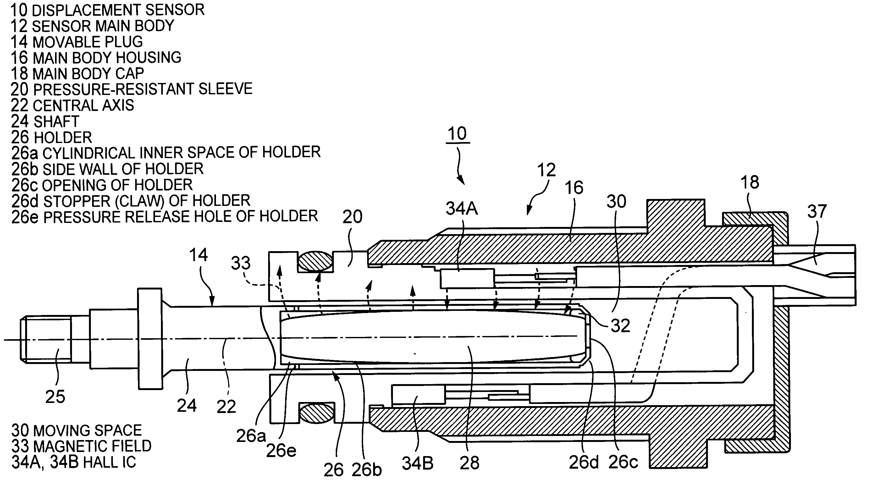
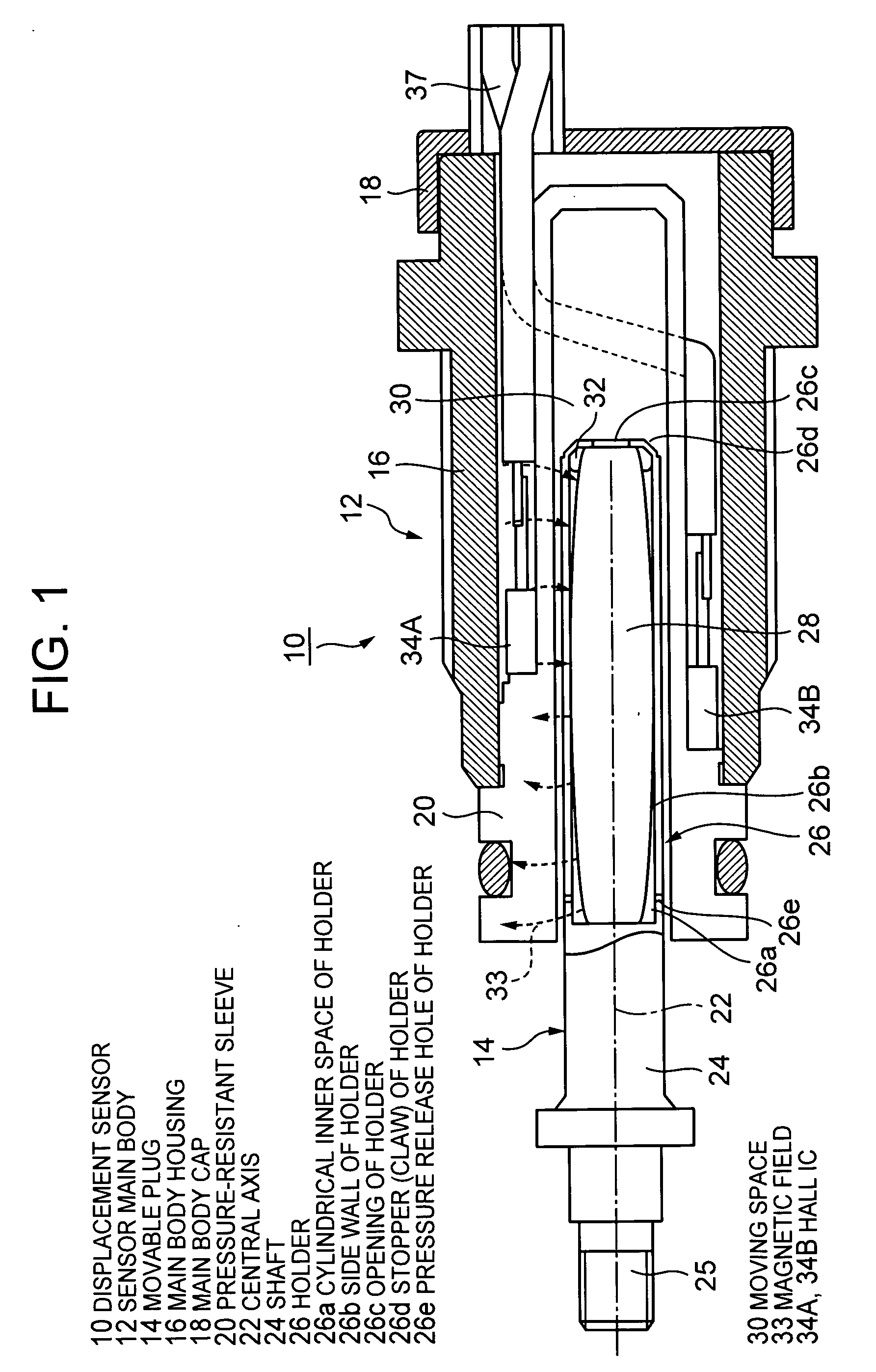
[0024]FIG. 1 is a sectional view of an embodiment of a displacement sensor using a magnetic field forming device according to the present invention. In the drawing, components illustrated by diagonal shading are made from magnetic materials. With the exception of a permanent magnet 28, components outlined in black are made from non-magnetic materials (for example, non-magnetic stainless steel, plastic, rubber, and so on).

[0025] As shown in FIG. 1, a displacement sensor 10 comprises a sensor main body 12, and a rod-form magnetism forming device (“movable plug” hereafter) 14 which is inserted into the sensor main body 12 so as to be capable of axial movement. The sensor main body 12 comprises a tubular main body housing 16 having openings at the front and rear ends, and a main body cap 18 which is fitted onto the rear end of the main body housing 16. The main body housing 16 and main body cap 18 are both made from magnetic materials, constitute the outer shell of the sensor main body...


PUM


Abstract

In a displacement sensor (10), a shaft (24) of a movable member (14) comprises a tubular part (26) having an opening (26c) at one end. A rod-form permanent is inserted into the tubular part (26) through the opening (26c) . A spacer (32) is fitted over a narrow portion of the rod-form magnet (28). The thickest portion of the magnet (28) and the spacer (32) contact the side wall of the tubular part (26) tightly, so that the magnet (28) is disposed coaxially with the tubular part (26). A stopper (26d) is formed on the opening (26c) of the tubular part (26), so that the magnet (28) does not move axially. Therefore, the magnet (28) is mounted in a prescribed position in a movable member (14) with a high degree of accuracy.

Description

CROSS-REFERENCE TO RELATED APPLICATIONS [0001] This application relates to and claims priority from Japanese Patent Application No. 2004-159996, filed on May 28, 2004, the entire disclosure of which is incorporated herein by reference. BACKGROUND OF THE INVENTION [0002] 1. Field of the Invention [0003] The present invention relates to a displacement sensor comprising a magnetic sensing device such as a Hall IC, and a magnetic field forming device for generating a magnetic field, which is capable of moving relative to the magnetic sensing device. The displacement sensor outputs f from the magnetic sensing device an electric signal having a level which corresponds to the relative displacement between the magnetic sensing device and the magnetic field forming device. [0004] The present invention also relates to a magnetic field forming device for providing a magnetic field in an exterior space using a magnetic member such as a permanent magnet. [0005] 2. Description of the Related Art ...

Claims


Application Information

Patent Timeline
IPC IPC(8): G01B7/02G01B7/14G01D5/12G01B7/30G01D5/14
CPCG01D5/145G01B7/003G01B7/31G01B7/14G01R27/2611
Inventor SHOJI, YUKIOYAMAMOTO, YUICHIYOSHIDA, NOBUMI
Owner KOMATSU LTD
Why Eureka
Try Eureka