Check patentability & draft patents in minutes with Patsnap Eureka AI!

Differential voltage controlled oscillator using complementary transistors cross-coupled in series, and transceiver using the same

a voltage control and oscillator technology, applied in the direction of oscillator, angle modulation by variable impedence, electrical equipment, etc., can solve the problems of increasing power consumption and current used by the vco, and achieve the effects of reducing the area of the integrated circuit, reducing the power consumption of the differential voltage controlled oscillator, and improving the phase noise respons

Active Publication Date: 2005-12-01
INFORMATION & COMM UNIV RES & INDAL COOPERATION GROUP
View PDF7 Cites 5 Cited by
  • Summary
  • Abstract
  • Description
  • Claims
  • Application Information

AI Technical Summary

Benefits of technology

[0011] It is a first advantage of the present invention to reduce power consumption of a differential voltage controlled oscillator.
[0012] It is a second advantage of the present invention to reduce an area of an integrated circuit into which the differential voltage controlled oscillator is realized.
[0013] It is a third advantage of the present invention to provide differential outputs with a single circuit structure.
[0014] It is a fourth advantage of the present invention to provide a differential voltage controlled oscillator with an improved phase noise response.
[0015] In one aspect of the present invention, a differential voltage controlled oscillator comprises: a first complementary transistor and a second complementary transistor having opposite magnitudes and directions of currents flowing to a third electrode from a second electrode in correspondence to a voltage applied between a first electrode and the second electrode; and a resonance circuit being coupled to the second electrodes of the first and second transistors and controlling a frequency of an oscillation signal corresponding to a control voltage, wherein the second electrode of the first transistor is coupled to the first electrode of the second transistor to form a first output terminal, the first electrode of the first transistor is coupled to the second electrode of the second transistor to form a second output terminal, and the third electrodes of the first and second transistors are respectively coupled to a first power and a second power.
[0016] The resonance circuit includes a first varactor and a second varactor each having one electrode for receiving the control voltage, and an inductor coupled between other electrodes of the first and second varactors.

Problems solved by technology

Therefore, the current used by the VCO is increased and the power consumption is increased.

Method used


Image

  • Differential voltage controlled oscillator using complementary transistors cross-coupled in series, and transceiver using the same
  • Differential voltage controlled oscillator using complementary transistors cross-coupled in series, and transceiver using the same
  • Differential voltage controlled oscillator using complementary transistors cross-coupled in series, and transceiver using the same

Examples


Embodiment Construction

[0032] In the following detailed description, only the preferred embodiment of the invention has been shown and described, simply by way of illustration of the best mode contemplated by the inventor(s) of carrying out the invention. As will be realized, the invention is capable of modification in various obvious respects, all without departing from the invention. Accordingly, the drawings and description are to be regarded as illustrative in nature, and not restrictive. To clarify the present invention, parts which are not described in the specification are omitted, and parts for which same descriptions are provided have the same reference numerals.

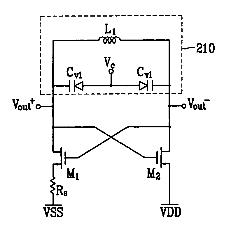
[0033] A differential voltage controlled oscillator (VCO) according to an exemplary embodiment of the present invention will use two complementary elements, that is, a first complementary element M1 and a second complementary element M2, respectively including a gate, a source, and a drain. The amount and direction of currents flowing to...


PUM


Abstract

A differential voltage controlled oscillator comprises first and second transistors having opposite magnitudes and directions of currents flowing to a third electrode from a second electrode corresponding to a voltage between first and second electrodes; and a resonance circuit coupled to the second electrodes of the first and second transistors and controlling a frequency of an oscillation signal corresponding to a control voltage. The second electrode of the first transistor is coupled to the first electrode of the second transistor to form a first output terminal, the first electrode of the first transistor is coupled to the second electrode of the second transistor to form a second output terminal, and the third electrodes of the first and second transistors are coupled to first and second powers.

Description

CROSS REFERENCE TO RELATED APPLICATION [0001] This application claims priority to and the benefit of Korea Patent Application No. 10-2004-39620 filed on Jun. 1, 2004 in the Korean Intellectual Property Office, the entire content of which is incorporated herein by reference. BACKGROUND OF THE INVENTION [0002] (a) Field of the Invention [0003] The present invention relates to a differential voltage controlled oscillator. More specifically, the present invention relates to a differential voltage controlled oscillator using cross-coupled complementary transistors, and a transceiver using the same. [0004] (b) Description of the Related Art [0005]FIG. 1 shows a conventional differential voltage controlled oscillator (VCO) including NMOS transistors M1 and M2, varactors Cv1 and Cv2, inductors L1 and L2, and a current source Iss. [0006] The NMOS transistors M1 and M2 are cross-coupled, the inductors L1 and L2 and the varactors Cv1 and Cv2 form a resonance circuit, one electrode of each of t...

Claims


Application Information

Patent Timeline
Patent Type & Authority Applications(United States)
IPC IPC(8): H03B1/00H03B5/12H03D7/16
CPCH03D7/165H03B5/1243H03B5/1212H03B5/1228H03B5/12
Inventor LEE, SANG GUGSHIN, SO BONGYUN, SEOK JU
Owner INFORMATION & COMM UNIV RES & INDAL COOPERATION GROUP
Features
  • R&D
  • Intellectual Property
  • Life Sciences
  • Materials
  • Tech Scout
  • Unparalleled Data Quality
  • Higher Quality Content
  • 60% Fewer Hallucinations
Learn More