Microstrip line type planar array antenna

a planar array and microstrip line technology, applied in the direction of individual energised antenna arrays, resonant antennas, antenna earthings, etc., can solve the problems of increasing the number of basic units described above, narrow frequency band width, and feeding loss, so as to reduce the number of powered antenna elements, increase the electromagnetic field intensity, and facilitate electromagnetic coupling

Inactive Publication Date: 2005-12-01
NIHON DEMPA KOGYO CO LTD +1
View PDF4 Cites 13 Cited by
  • Summary
  • Abstract
  • Description
  • Claims
  • Application Information

AI Technical Summary

Benefits of technology

[0020] It is therefore an object of the present invention to provide a planar array antenna of a microstrip line type which can reduce the number of powered antenna elements and has an improved antenna gain.
[0022] Since the powered element pair in which the powered antenna element and the first passive element oppose to each other via the dielectric substrate and the passive element pair in which the adjacent antenna element and the second first passive element oppose to each other via the dielectric substrate with the same condition adjoin to each other in the array antenna according to the present invention, the powered element pair and the passive element pair are easily electromagnetically coupled to each other. For example, the passive element pair easily receives the leak electromagnetic field from the powered element pair and both pairs are electromagnetically coupled to each other easily. Since the passive element pair is disposed in an electric field plane direction or a magnetic field direction of the electromagnetic wave emitted from the powered element pair, the powered element pair and the passive element pair electromagnetically couple to each other directly. As a result, the passive element also emits the electromagnetic wave with increased electromagnetic field intensity at the antenna frequency. Then the electromagnetic waves from the powered element pair and the passive element pair are combined and emitted. As a result, a planar array antenna having an antenna gain equivalent to that of a conventional array antenna in which all antenna elements are powered antenna elements is obtained. According to the present invention, it is possible to reduce the number of powered antenna elements to which high frequency power is supplied while improving the antenna gain.
[0023] In the present invention, it is preferable to construct a basic unit by two sets of the powered element pairs and a plurality sets of the passive element pairs. It is preferable to provide, in the basic unit, a first feeding line consisting of a microstrip-line which connects at both ends thereof to two powered antenna elements, and a second feeding line consisting of a slot line formed in said ground conductor, the second feeding line traversing a midpoint of the first feeding line and electromagnetically coupled to the first feeding line. In this case, the high frequency power from a feeding end of the second feeding line branches in opposite phase to opposing directions in the electric field from the midpoint of the first feeding line, and then is supplied to two powered antenna elements. As a result, the two powered antenna elements are excited in-phase and emits electromagnetic wave with the same polarization plane. Therefore, by utilizing the above basic units, impedance matching in the feeding system is facilitated and the structure of the feeding system is simplified.
[0024] According to the present invention, it is possible to easily construct an planar array antenna with numbers of elements by using a plurality pieces of the basic units described above and combining an opposite-phase branch to a microstrip line from a slot line and an in-phase branch to a slot lint from a microstrip line to configure the feeding system. In such a multi-element planar array antenna, it is possible to improve the antenna gain while suppress the increase in the number of the powered antenna elements.

Problems solved by technology

The planar array antenna described above has, however, an disadvantage that it basically has a narrow frequency band width because each powered antenna element is an antenna element of a microstrip line type.
However, in this configuration, as the number of the antenna elements is increased for improving the antenna gain, the number of the basic units described above is also increased and the feeding loss is increased.

Method used


Image

  • Microstrip line type planar array antenna
  • Microstrip line type planar array antenna
  • Microstrip line type planar array antenna

Examples


first embodiment

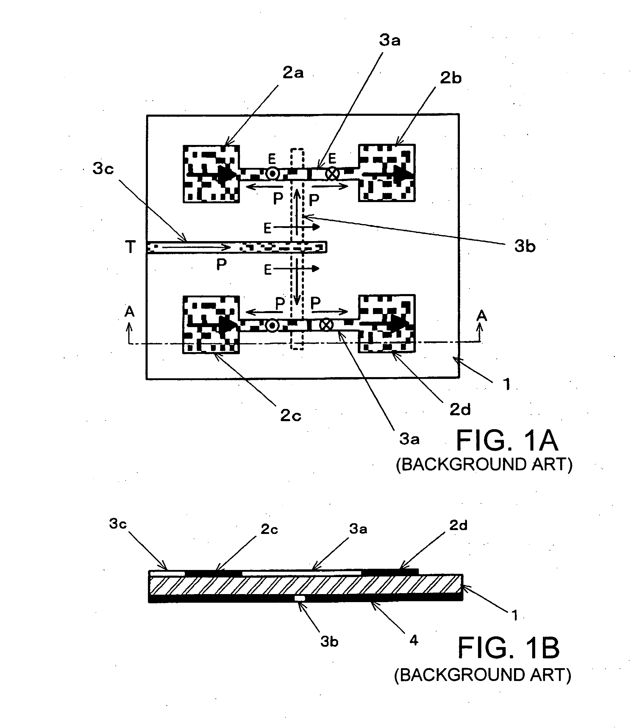
[0059]FIGS. 4A to 4C illustrate a microstrip line type planar array antenna according to the present invention and show the construction of the basic unit used in this planar array antenna. It should be noted that, in FIGS. 4A to 4C, those parts which are identical to those shown in FIGS. 1A to 1C are denoted by identical reference characters and the duplicate explanations thereon are simplified.

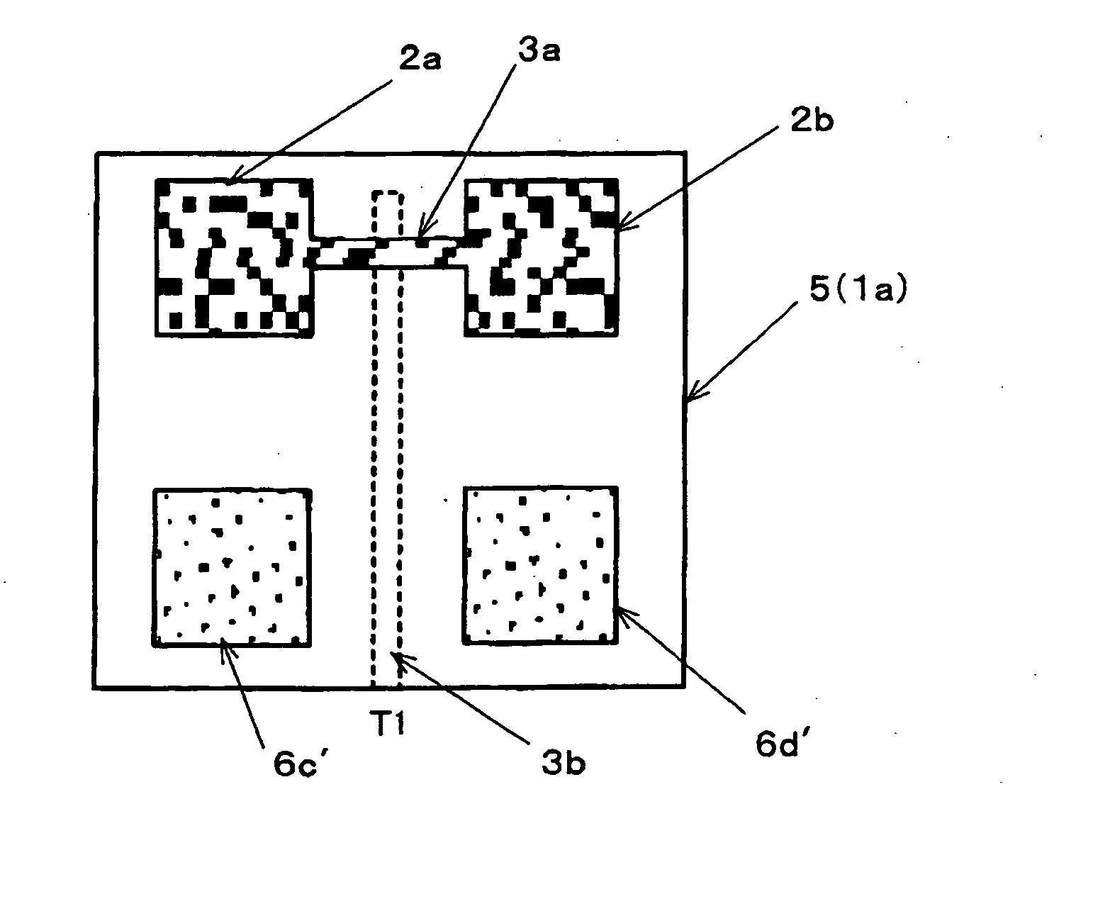
[0060] In the basic unit shown in FIGS. 4A to 4C, first and second substrates 1a, 1b each consisted of a dielectric material are stacked and constitutes multilayer substrate 5. On the plane sandwiched by first substrate 1a and second substrate 1b, that is, an intermediate layer, two pieces of powered antenna elements 2a, 2b are arranged at the positions corresponding to the both ends of one side of a geometric square, for example, a regular square, and two pieces of adjacent passive element 6c′, 6d′ are arranged at the two remaining apexes of the regular square. In the example shown in the f...

second embodiment

[0076]FIGS. 8A to 8C illustrate a microstrip line type planar array antenna according to the present invention and show the construction of the basic unit used in this planar array antenna. It should be noted that, in FIGS. 8A to 8C, those parts which are identical to those shown in FIGS. 4A to 4C are denoted by identical reference characters and the duplicate explanations thereon are simplified.

[0077] Also with the second embodiment, in the basic unit, first and second substrates 1a, 1b each consisted of a dielectric material are stacked and constitute multilayer substrate 5. Ground conductor 4 is provided on the reverse surface of multilayer substrate 5. On the plane sandwiched by first substrate 1a and second substrate 1b, that is, an intermediate layer, powered antenna elements 2a, 2b are arranged at the positions corresponding to the midpoints of the longer sides of a rectangle, respectively, and adjacent passive elements 6c′, 6d′, 6e′, 6f′ are arranged at the positions corresp...

third embodiment

[0083]FIGS. 10A to 10C illustrate a microstrip line type planar array antenna according to the present invention and show the construction of the basic unit used in this planar array antenna. It should be noted that, in FIGS. 10A to 10C, those parts which are identical to those shown in FIGS. 4A to 4C are denoted by identical reference characters and the duplicate explanations thereon are simplified.

[0084] Also with the third embodiment, in the basic unit, first and second substrates 1a, 1b each consisted of a dielectric material are stacked and constitute multilayer substrate 5. Ground conductor 4 is provided on the reverse surface of multilayer substrate 5. On the plane sandwiched by first substrate 1a and second substrate 1b, that is, an intermediate layer, powered antenna elements 2a, 2b are arranged at the positions corresponding to both ends of a diagonal of a regular square or a rectangle, respectively, and adjacent passive elements 6c′, 6d′ are arranged at the positions corr...


PUM


Abstract

A planar array antenna comprises a powered antenna element and an adjacent passive element which are microstrip-line type ones and disposed on one principal surface of a dielectric substrate; and a feeding system for feeding high frequency power to the powered antenna element. The powered antenna element and a passive element disposed ahead of the powered antenna element constitute a powered element pair, and the adjacent passive element and a passive antenna element disposed ahead of the adjacent passive element constitute a passive element pair. The passive element pair is disposed so that it adjoins said powered element pair in an electric field direction or a magnetic field direction of radio wave emitted from the powered antenna element.

Description

BACKGROUND OF THE INVENTION [0001] 1. Technical Field of the Invention [0002] The present invention relates to a planar array antenna having microstrip-line antenna elements, which is primarily applied in millimeter wave and microwave bands, and more particularly to a planar array antenna which has an improved high antenna gain and maintains a wide bandwidth. [0003] 2. Description of the Related Art [0004] With the developments in radio communication technologies, especially mobile communications, antennas are required to be of higher performance and smaller size. Planar antennas are widely used in millimeter wave and microwave bands. Planar antennas are generally grouped into microstrip-line antennas and slot-line antennas. Of these planar antennas, microstrip-line planar antennas are small in size and can easily be manufactured, and has a feature that it can be produced at low cost and the like. However, since microstrip-line planar antennas have a relatively low antenna gain, it ...

Claims


Application Information

Patent Timeline
Patent Type & Authority Applications(United States)
IPC IPC(8): H01Q1/38H01Q9/04H01Q13/08H01Q19/00H01Q21/06
CPCH01Q9/0414H01Q21/065H01Q19/005
Inventor NISHIYAMA, EISUKEAIKAWA, MASAYOSHIASAMURA, FUMIOOITA, TAKEO
Owner NIHON DEMPA KOGYO CO LTD
Why Eureka
Try Eureka