Radio network, relay node, core node, relay transmission method used in the same and program thereof

a relay transmission and radio network technology, applied in data switching networks, multiplex communication, high-level techniques, etc., can solve the problems of narrowing the service area in each node, reducing the diffractive effect of radio waves, and difficulty in non line-of-sight communication

Inactive Publication Date: 2005-12-01
NEC CORP
View PDF8 Cites 20 Cited by
  • Summary
  • Abstract
  • Description
  • Claims
  • Application Information

AI Technical Summary

Benefits of technology

[0014] The present invention addresses the problem set forth above. It is therefore an object of the present invention to provide a radio network, a relay node, a core node, a relay transmission method used in the same and a program thereof, which can select a route of minimum path loss among entire relay routes, and can set the relay route to resist satisfactorily resist interference.

Problems solved by technology

When frequency becomes higher, diffraction effect of the radio wave is reduced to make straightening characteristics significant, and it causes difficulty in non line-of-sight communication to inherently narrow the area of service in each node.
However, in order for a connection between a large number of geographically concentrated nodes and the backbone network, wire line networks have to be extended to every place, thus inherently increasing the cost of the overall system.
In a route method that decreases the number of relay nodes, the so-called “minimum hop routing” method, throughput or system capacity cannot be always at maximum relaying route for lacking of reception power due to the distance between relay nodes and obstacles.

Method used


Image

  • Radio network, relay node, core node, relay transmission method used in the same and program thereof
  • Radio network, relay node, core node, relay transmission method used in the same and program thereof
  • Radio network, relay node, core node, relay transmission method used in the same and program thereof

Examples


Embodiment Construction

[0152] The present invention will be discussed hereinafter in detail in terms of the preferred embodiment of the present invention with reference to the accompanying drawings. In the following description, numerous specific details are set forth in order to provide a thorough understanding of the present invention. It will be obvious, however, to those skilled in the art that the present invention may be practiced without these specific details. Well-known structures are not shown in detail in order to avoid unnecessary obscurity of the present invention.

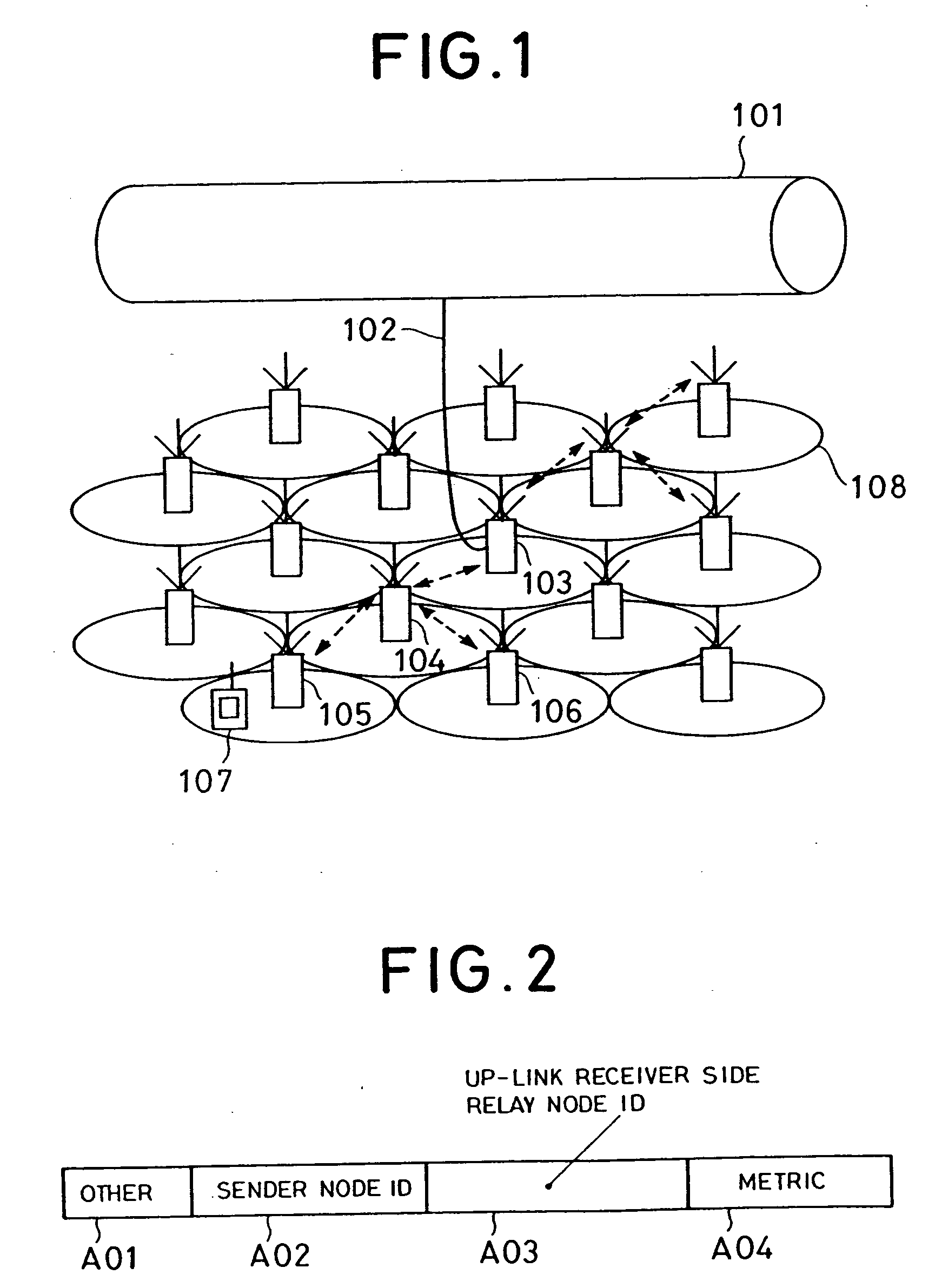
[0153]FIG. 1 is a diagrammatic illustration showing one embodiment of a cellular system according to the present invention. In FIG. 1, the reference numeral 107 denotes a terminal station, and reference numeral 108 denotes a cell. A core node 103 and a wired backbone 101 are connected by wire circuit 102. Relay nodes 104 to 106 are connected to the core node 103 by radio relay.

[0154] Each of the relay nodes and the core node may b...


PUM


Abstract

A radio network can select a route of minimum path loss among entire relay routes and can set the relay route so as to satisfactorily resist interference. The radio network has a core node connected to a wired network, relay nodes each relaying at least one of a down-link data packet transmitted from the core node and an up-link data packet directed toward the core node, and a terminal station capable of transmission and reception of data packets with both the core node and the relay node. The relay node has total path loss optimized to be minimum between relay nodes included in a relay route of the data packet or between the relay node and the core node or both.

Description

CROSS REFERENCE TO RELATED APPLICATIONS [0001] This application is a Divisional of application Ser. No. 09 / 942,408, filed Aug. 29, 2001, entitled RADIO NETWORK, RELAY NODE, CORE NODE, RELAY TRANSMISSION METHOD USED IN THE SAME AND PROGRAM THEREOF, the entire disclosure of which is incorporated herein by reference.BACKGROUND OF THE INVENTION [0002] 1. Field of the Invention [0003] The present invention relates generally to a radio network, a relay node, a core node, a relay transmission method used in the same and a program thereof. More particularly, the invention relates to a relay route setting method and a relay transmission method in a cellular system, in which a plurality of nodes are connected by a radio network. [0004] 2. Description of the Related Art [0005] A cell structure in the conventional cellular system is illustrated in FIG. 20. In FIG. 20, the reference numeral 401 denotes a cell and 402 denotes a base station (node). As shown in FIG. 20, a service area is construct...

Claims


Application Information

Patent Timeline
Patent Type & Authority Applications(United States)
IPC IPC(8): H04B7/26H04J3/14H04L12/28H04L12/701H04L12/725H04W16/26H04W16/28H04W92/20
CPCH04B7/155H04L45/00H04W16/14H04W28/04H04W40/06H04W40/08Y02B60/50H04W40/16H04W40/22H04W40/248H04W84/00H04W88/04H04W40/12Y02D30/70
Inventor FURUKAWA, HIROSHIMOMONA, MORIHISAEBATA, KOICHI
Owner NEC CORP
Why Eureka
Try Eureka