Printed board drilling method and printed board machining apparatus

a printing board and machining technology, applied in the direction of drilling/boring measurement devices, manufacturing tools, instruments, etc., can solve the problems of reducing machining efficiency, reducing machining quality, and prone to breakage of drills, so as to improve machining quality and work efficiency, and minimize the runout of the drill tip.

Inactive Publication Date: 2005-12-01
HITACHI SEIKO LTD
View PDF22 Cites 15 Cited by
  • Summary
  • Abstract
  • Description
  • Claims
  • Application Information

AI Technical Summary

Benefits of technology

[0024] It is therefore an object of the invention to solve the aforementioned problems by providing a printed board drilling method and a printed board machining apparatus that are capable of improving the machining quality and work efficiency by minimizing the runout of the tip of the drill.

Problems solved by technology

When the runout z of the tip of the drill becomes significant, not only the machining quality such as positional accuracy of holes and true roundness of drilled holes degrade but also the machining efficiency drops because drills are apt to be broken.

Method used


Image

  • Printed board drilling method and printed board machining apparatus
  • Printed board drilling method and printed board machining apparatus
  • Printed board drilling method and printed board machining apparatus

Examples


first embodiment

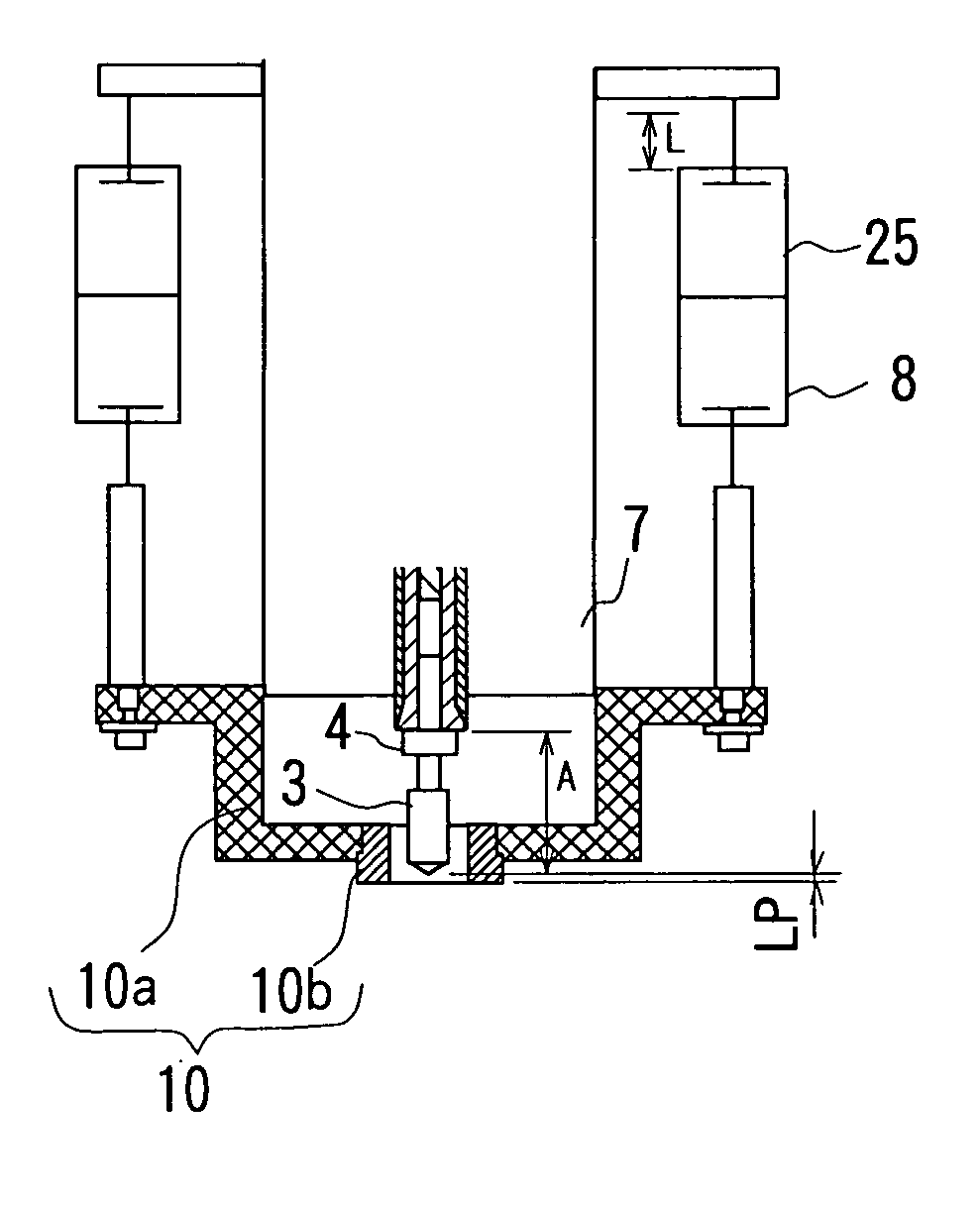
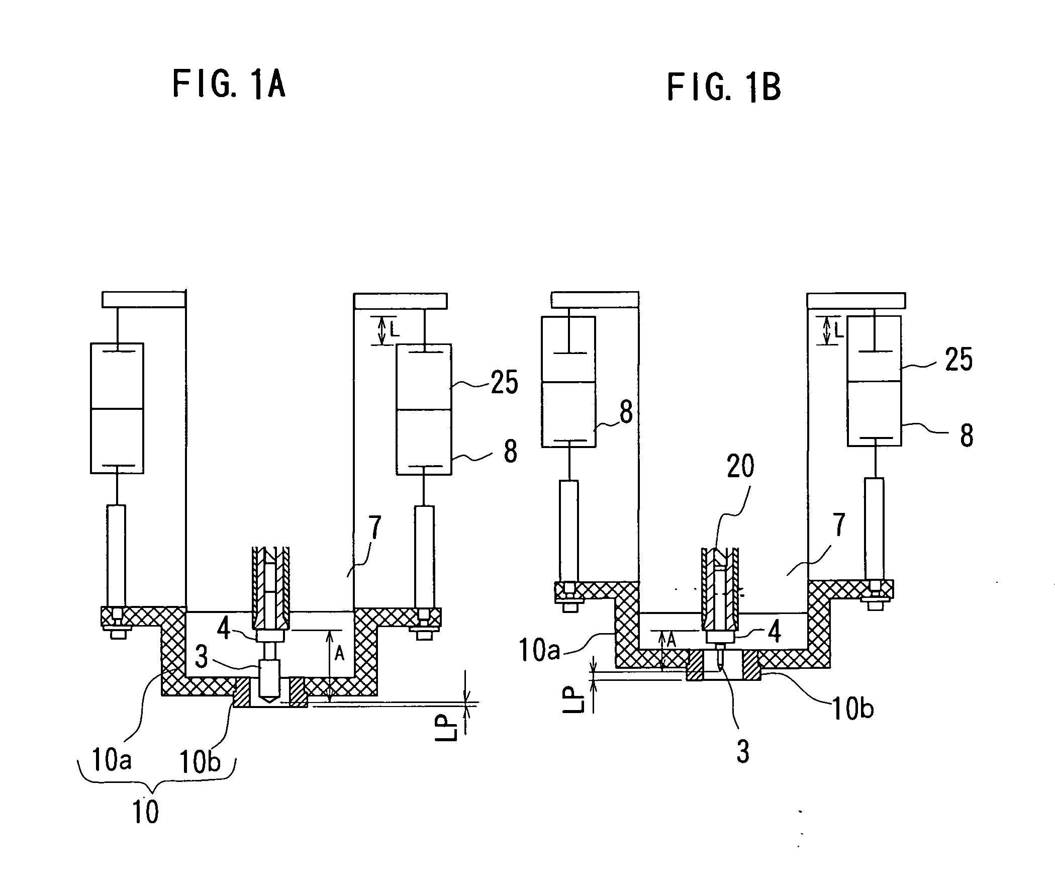
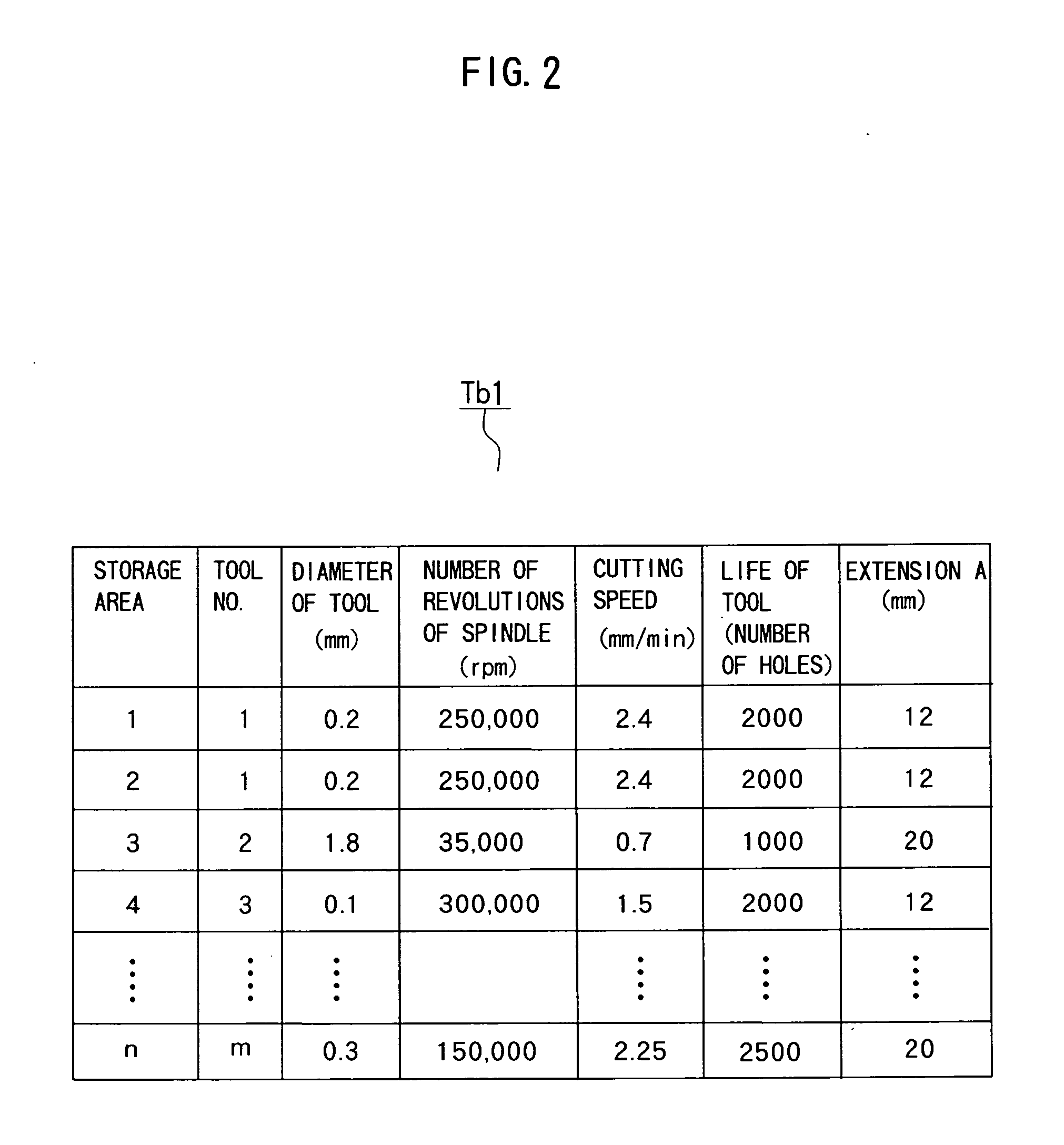
[0049]FIGS. 1A and 1B are front views showing a main part of a printed board machining apparatus of the invention and FIG. 2 is a table showing stored contents of record of a machining condition data table of the invention. It is noted that the same components or functions with those in FIG. 5 are denoted by the same reference numerals and an overlapping explanation thereof will be omitted here.

[0050] As shown in FIGS. 1A and 1B, a spindle head (spindle moving means) 7 supports a first cylinder (pressure foot positioning means) 8 through an intermediary of a second cylinder (pressure foot positioning means) 25. A pressing force of the second cylinder 25 is fully greater than that of the first cylinder 8. A stroke of the second cylinder 25 is L (8 mm here).

[0051] A pressure foot 10 is composed of a body 10a and a head bush 10b that is removably attached to the body 10a.

[0052] As shown in FIG. 2, data showing Extension A per type and mode of use of drills is added to a tool data ta...

second embodiment

[0061] Next, a case of setting the drill extension A by means of a stopper (abutting position setting means) 20 within the spindle head will be explained.

[0062] In setting the drill extension A by means of the stopper 20, position of the stopper 20 must be changed corresponding to the extension A of the specified drill.

[0063] In this case, the stopper 20 may be arranged so as to be movable in the axial direction or a member movable in the radial direction may be provided axially in front of the end face of the stopper 20 within the collet. The drill extension A may be shortened by moving the movable member to position the drill and the drill extension A may be prolonged by abutting the rear end of the drill against the stopper.

[0064] The invention is applicable also to a conventional spindle because the position of the stopper needs not to be changed by providing a drill whose whole length is short.

third embodiment

[0065] A third embodiment which is a partial modification of the first and second embodiments described above will be explained in succession with reference to FIGS. 3 and 4. FIG. 3 is a side view of the main part of the printed board machining apparatus according to the third embodiment of the invention and FIG. 4 is a section view taken along B-B in FIG. 3. It is noted that the same components with those in the first and second embodiments are denoted by the same reference numerals and an explanation thereof will be omitted here.

[0066] The printed board machining apparatus of the third embodiment has a guide mechanism (pressure foot positioning means) 100 instead of the second cylinder 25 described above. Still more, the pressure foot 10 is partially changed and is connected with a vacuum source (suction means) not shown through an intermediary of a joint 80 and a suction port 81 provided therein.

[0067] The guide unit 100 is composed of a base 50, a servo motor 52, a ball thread...


PUM

PropertyMeasurementUnit
diameteraaaaaaaaaa
diameteraaaaaaaaaa
diameteraaaaaaaaaa

Abstract

There are provided a printed board drilling method and a printed board machining apparatus that are capable of improving machining quality, such positional accuracy of holes and true roundness of machined holes, and work efficiency by minimizing a runout of the tip of a drill. An extension of the drill extending out a spindle when the drill is held by the spindle is defined in advance per type or mode of use of each drill. One drill is selected among a plurality of drills corresponding to a shape of holes to be drilled in the printed board and the spindle is caused to hold the drill so that the selected drill extends out of the spindle by the extension corresponding to the selected drill. Then, the move of the spindle with respect to the printed board is controlled and the selected drill is rotationally driven by the spindle to drill the printed board.

Description

BACKGROUND OF THE INVENTION [0001] 1. Field of the Invention [0002] The present invention relates to a printed board drilling method and a printed board machining apparatus for machining holes in a printed board by using drills. [0003] 2. Description of Related Art [0004] The size of holes drilled in a printed board are required to be highly accurate in the depth direction. Then, Japanese Patent No. 2559788 has disclosed a machining apparatus that calculates a distance between a head of a pressure foot and the tip of a tool in advance of machining and controls a feed distance of a spindle head based on that distance. This technology will be explained below. [0005]FIG. 5 is a front section view of a main part of the conventional printed board machining apparatus. [0006] As shown in FIG. 5, a printed board 1 is fixed on a table 2. A ring 4 is attached around a drill 3. The drill 3 is rotatably held by a spindle 6 through an intermediary of a collet 5. An edge of the collet 5 forms one...

Claims


Application Information

Patent Timeline
Patent Type & Authority Applications(United States)
IPC IPC(8): B23Q15/24B23Q17/22H05K3/00
CPCB23Q17/2233H05K3/0047H05K2203/0207Y10T408/175Y10T408/03Y10T408/36Y10T408/50Y10T408/5623B23B41/00B23B49/00B23B39/00
Inventor SUZUKI, NOBUHIKONAGASAWA, KATSUHIRO
Owner HITACHI SEIKO LTD
Why Eureka
Try Eureka