Ramp signal with boost portion preceding a time slot

a boost signal and time slot technology, applied in the field of transmitters, can solve the problems of increasing the useable portion of a time slot, and achieve the effects of reducing switching transients produced, enhancing control signals, and charging more quickly

Inactive Publication Date: 2005-12-01
NOKIA SOLUTIONS & NETWORKS OY
View PDF9 Cites 55 Cited by
  • Summary
  • Abstract
  • Description
  • Claims
  • Application Information

AI Technical Summary

Benefits of technology

[0014] In this manner, an enhanced control signal is supplied to the power controller during the boost portion. This allows capacitive components in the power controller to be charged more quickly, so that the control of the power amplifier can begin follow the control signal at an earlier time when compared with prior art a

Problems solved by technology

When used in a transmitter configured to transmit data in time slots,

Method used


Image

  • Ramp signal with boost portion preceding a time slot
  • Ramp signal with boost portion preceding a time slot
  • Ramp signal with boost portion preceding a time slot

Examples


Embodiment Construction

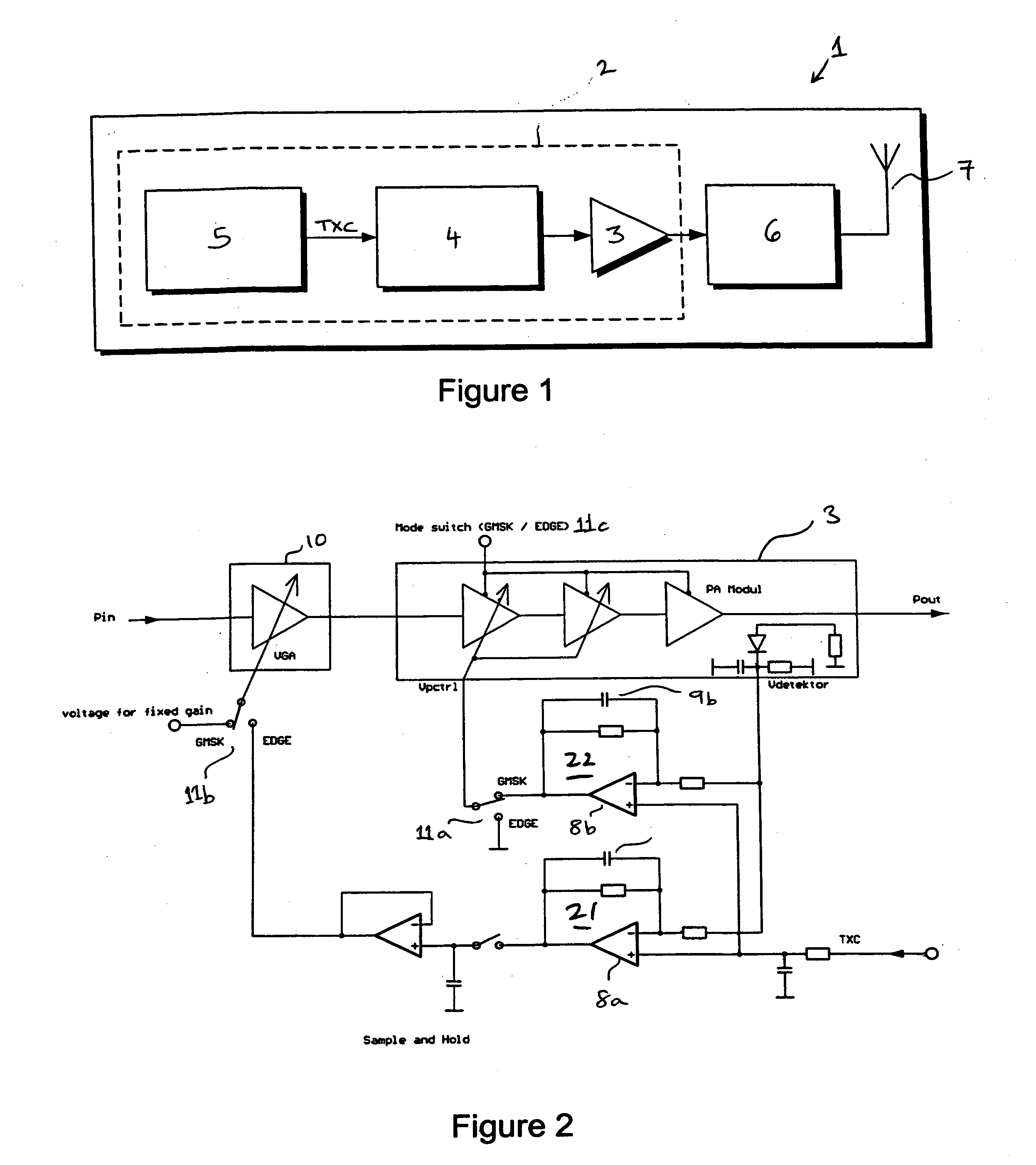
[0027] A transmitter 2 comprises a power amplifier 3 and a power controller 4, as shown in FIGS. 1 and 2. The power amplifier 3 is capable of both linear and non-linear operation and is controlled by first and second control loops as described above in relation to the prior art.

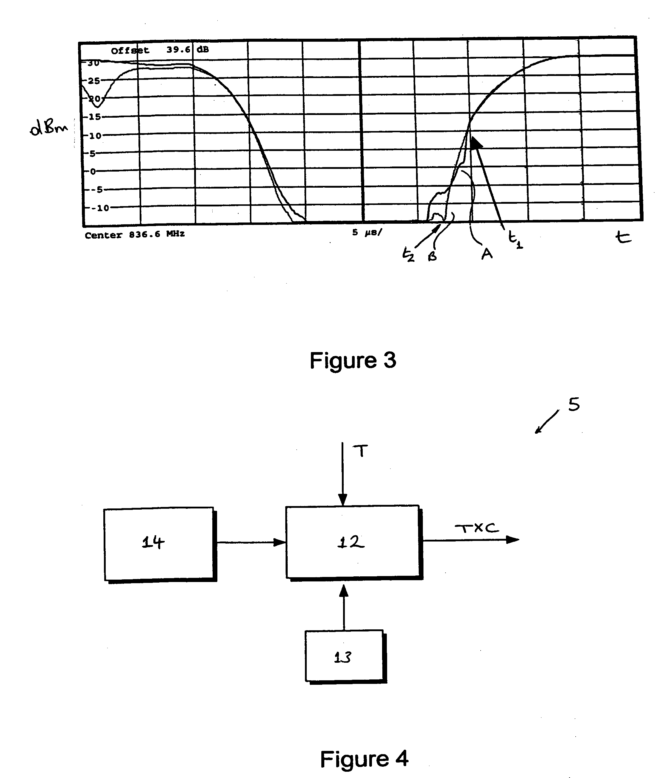
[0028]FIG. 4 shows the ramp generation circuit 5 of the transmitter 2 of the first embodiment in more detail. The ramp generation circuit 5 comprises a signal generator 12 with an associated clock 13 and a memory facility, such as ROM 14. The ROM 14 stores ramp data values based on samples of a predetermined ramp shape. If required, the signal generator 12 may include interpolating means for generating extra ramp values from the ramp data values stored in the ROM 14.

[0029] An example set of ramp data values is represented in FIG. 5. The tamp shape is based on a generally regular profile C (also labelled ‘prior method’). The generally regular profile C may be based on a trigonometric formula such as a cos2 o...


PUM


Abstract

A transmitter includes a power amplifier which is capable of both linear and non-linear operation, controlled by first and second control loops. A power controller includes a capacitive component, and controls the gain of the power amplifier. A ramp generation circuit provides a control signal to the power controller. It includes a ROM which stores ramp data values based on samples of a predetermined ramp shape. The ramp shape is based on a generally regular profile C, for example a cos2 or cos4 function. The ramp shape also includes a boost portion BP, which enhances the ramp data values before the beginning of the generally regular profile C. The boost portion BP causes the capacitor in the feedback loop of the relevant control loop to become fully charged more rapidly, which produces a corresponding increase in the output power of the power amplifier shortly after the generally regular profile C is applied. This allows the transmitter to follow the generally regular profile C of the ramp signal at an earlier time when compared with the prior art. The size of the boost portion BP can be adjusted dependent on a detected temperature.

Description

FIELD OF THE INVENTION [0001] The invention relates to a transmitter, and to a method in which power provided by a transmitter is controlled on the basis of a control signal. BACKGROUND OF THE INVENTION [0002]FIG. 1 depicts a communication device 1 arranged to transmit data in a series of time slots, such as a TDMA system. The communication device 1 comprises a transmitter 2 that includes a power amplifier 3, a power controller 4 arranged to control the power amplifier 3 and a control signal generator 5 that provides a control signal TXC to the power controller 4, together with a TX-RX switch 6 and antenna 7. The power amplifier 3 supplies power to the antenna 7. The antenna 7 is activated at the start of a given time slot and deactivated at the end of that time slot. Of course, TX-RX switch 6 also is connected to a receiver (not shown). [0003] While it is desirable to maximise a portion of the time slot that can be used for data transmission, that is, the portion of the time slot d...

Claims


Application Information

Patent Timeline
IPC IPC(8): H03F1/02H03F1/06H04B1/02H04B1/04
CPCH03F1/0205H03F1/0211H04B2001/0416H03F1/0277H04B1/04H03F1/0244
Inventor WEISS, MANFRED
Owner NOKIA SOLUTIONS & NETWORKS OY
Why Eureka
Try Eureka