2D and 3D display system and method for furnace tube inspection

a technology of display system and furnace tube, which is applied in the direction of furnaces, instruments, nuclear elements, etc., can solve the problems of difficult correlation of inspection data collected from the furnace with the physical geometry of the furnace, inspection tools may take longer to traverse a bend in the furnace, and inspection tools often ebb and flow through the furnace, etc., to facilitate the observation of trends and rapid assessment of problem areas

Active Publication Date: 2005-12-01
QUEST INTEGRITY USA LLC
View PDF5 Cites 22 Cited by
  • Summary
  • Abstract
  • Description
  • Claims
  • Application Information

AI Technical Summary

Benefits of technology

[0016] The present invention has several advantages over the prior art. For example, the invention provides a processing and display methodology that allows a large amount of inspection data to be correlated with the physical geometry of the furnace. In addition, the invention provide...

Problems solved by technology

One problem with the furnace tube inspection systems of the prior art is that it is difficult to correlate the inspection data collected from the furnace with the physical geometry of the furnace.
Instead, the inspection tool will often ebb and flow through the furnace and/or may become momentarily stuck at a point in the structure.
Also, the inspection tool may take longer to traverse a bend in the furnace.
In addition, the furnace may change in schedule size or diameter and thus retard or promote the passing of the inspection tool.
All of these conditions generate a correlation (i.e., mapping or scaling) problem between the collected inspection data and the precise location of the inspection tool with respect to the physical geometry of the furnace.
As a result, an engineer may not be able to identify the precise locations of the worn sections and/or hot spots of the furnace.
Another problem with the furna...

Method used


Image

  • 2D and 3D display system and method for furnace tube inspection
  • 2D and 3D display system and method for furnace tube inspection
  • 2D and 3D display system and method for furnace tube inspection

Examples


example 1

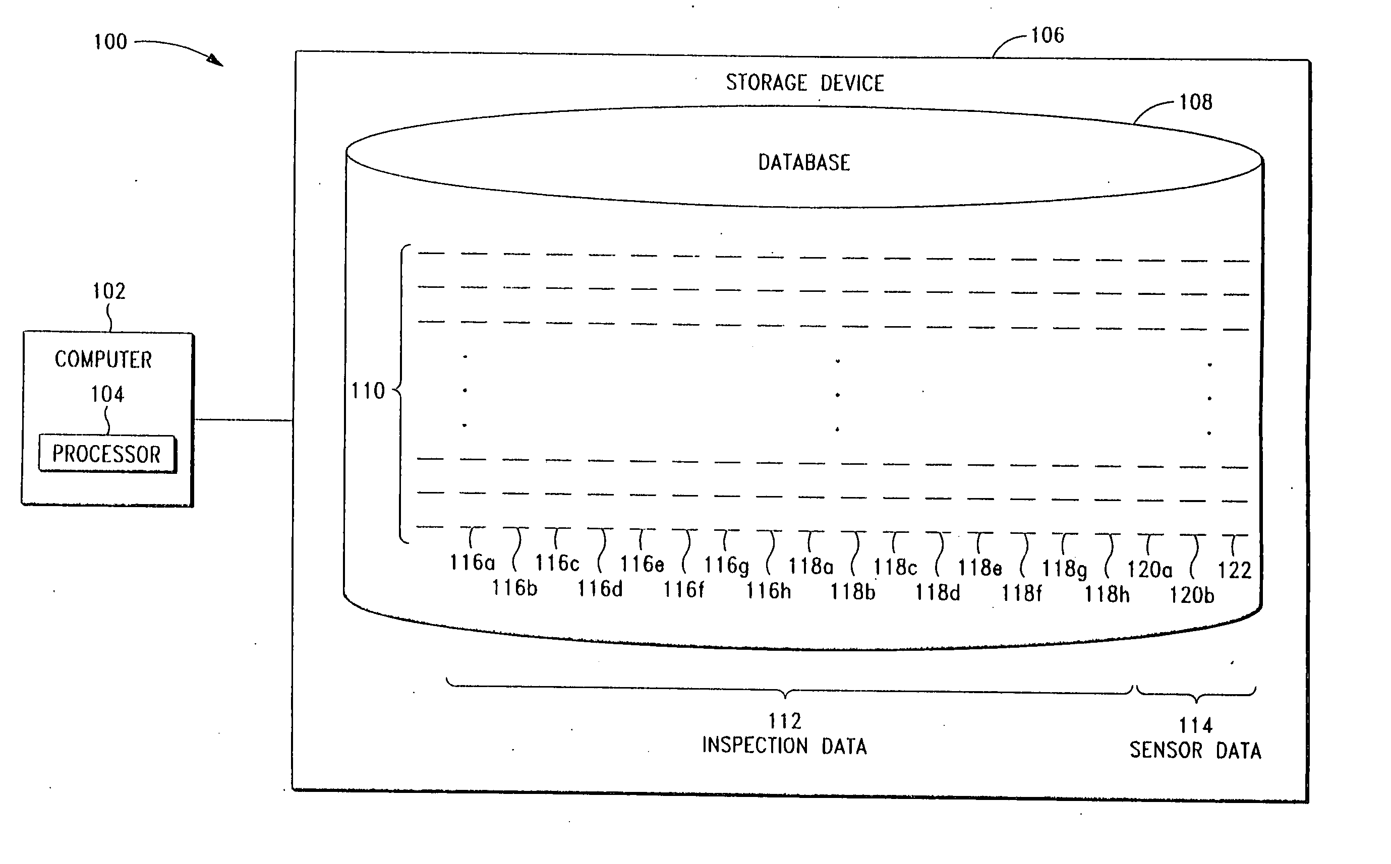
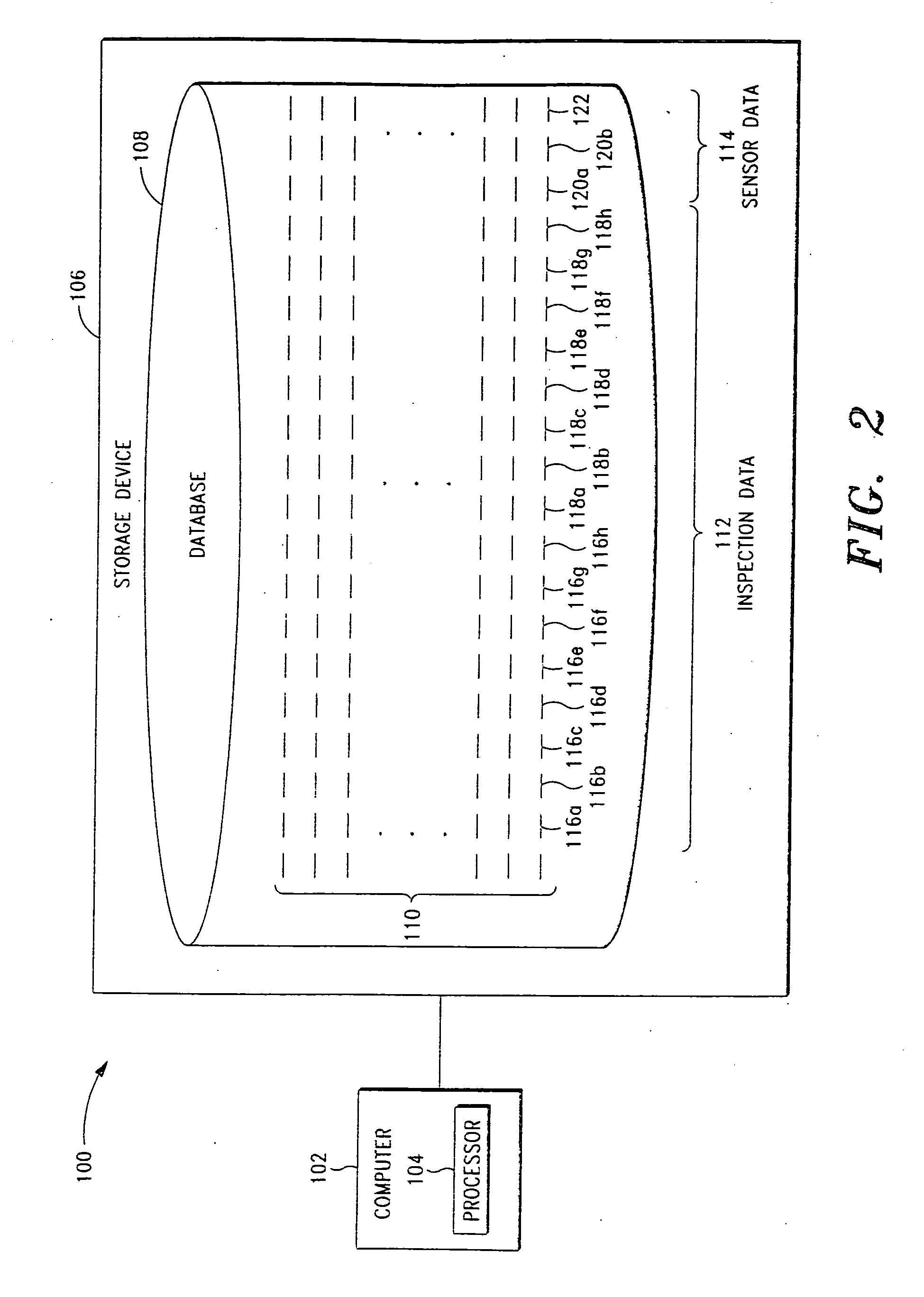
[0052] In this example, computer 102 is programmed to generate a two-dimensional display of the wall thickness readings and / or inside radius readings collected from a furnace, which may be viewed by a data analyst in order to identify the locations of the furnace bends. Then, based upon input from the data analyst, computer 102 is programmed to generate a plurality of data markers on the display to thereby correlate the various readings to the appropriate tube segments of the furnace. After generation of the data markers, the data analyst may view the display in order to visually detect problems areas within the furnace. This example will now be described in greater detail with reference to FIGS. 3 and 4.

[0053] Referring to FIG. 3, computer 102 is programmed to generate a strip chart 300 in which all of the wall thickness readings for a plurality of time intervals are plotted across a plurality of horizontal strips. The wall thickness readings are plotted successively in time from ...

example 2

[0062] In this example, computer 102 is programmed to generate a two-dimensional display of the wall thickness readings collected from the convection section of a furnace, whereby the display may be viewed by a data analyst in order to visually detect problems areas within the furnace. Specifically, computer 102 is programmed to generate the chart shown in FIG. 5, in which all of the wall thickness readings for a plurality of time intervals are plotted across a plurality of vertical bars. Each vertical bar displays the wall thickness readings from a single tube segment. The tube segments are positioned in their proper orientation (but with the connecting bends removed).

[0063] In this example, the wall thickness readings displayed on the chart are color-coded in accordance with a color legend, wherein the readings range from 3 mm (shown in dark red) to 10 mm (shown in dark blue). It should be understood that the wall thickness readings may alternatively be represented in gray scale ...

example 3

[0065] In this example, computer 102 is programmed to generate a two-dimensional display of the wall thickness readings collected from the convection section of another furnace, whereby the display may be viewed by a data analyst in order to visually detect problems areas within the furnace. Specifically, computer 102 is programmed to generate the chart shown in FIG. 6, in which all of the wall thickness readings for a plurality of time intervals are plotted across a plurality of vertical bars. Similar to the chart of FIG. 5, each vertical bar displays the wall thickness readings from a single tube segment, wherein the tube segments are positioned in their proper orientation (but with the connecting bends removed).

[0066] In this example, the wall thickness readings displayed on the chart are color-coded in accordance with a color legend, wherein the readings range from 0.20 inches (shown in dark red) to 0.45 inches (shown in dark blue). Again, while the wall thickness readings may ...


PUM


Abstract

A system and method for displaying inspection data collected from a furnace is disclosed. The system comprises a storage device for storing the inspection data. The system also comprises a computer programmed to partition the inspection data at a plurality of data markers so as to correlate the inspection data to the physical geometry of the furnace. Each of the data markers identifies the location of a physical feature of the furnace (such as a bend, an external raised surface, cross-over piping, a thermal well, a weld, a flange, a schedule change and/or a diameter change). Preferably, the computer is also programmed to generate a display of the partitioned inspection data, wherein the display is a two-dimensional or three-dimensional representation of the tube segments of the furnace. This display may then be used to visually detect problem areas within the furnace. Various exemplary embodiments of the system and associated method are provided.

Description

CROSS-REFERENCE TO RELATED APPLICATIONS [0001] This application claims priority to U.S. Provisional Patent Application Ser. No. 60 / 576,276, filed Jun. 1, 2004, entitled “2D and 3D Display System and Method for Furnace Tube Inspection,” which is incorporated herein by reference.STATEMENT REGARDING FEDERALLY SPONSORED RESEARCH OR DEVELOPMENT [0002] Not Applicable. BACKGROUND OF THE INVENTION [0003] 1. Field of the Invention [0004] The present invention relates generally to furnace tube inspection systems, and more particularly to a system and method for displaying inspection data in a two-dimensional and / or three-dimensional format to enable visual detection of problem areas within the furnace. [0005] 2. Description of Related Art [0006] As depicted in FIGS. 1A-1C, a furnace is generally comprised of several hundred to several thousand feet of serpentine tubing that is characterized by straight tube segments (each of which is identified as reference numeral 10) interconnected by angle...

Claims


Application Information

Patent Timeline
IPC IPC(8): F27D19/00F27D21/00G06F19/00
CPCF27D19/00G01N2291/2636G01N29/4454F27D21/00
Inventor BONDURANT, PHILLIP D.DE LORENZO, ROBERTROBERTS, RICHARD D.
Owner QUEST INTEGRITY USA LLC
Why Eureka
Try Eureka