Multiple branch predictions

Active Publication Date: 2005-12-01
ORACLE INT CORP
11 Cites 108 Cited by

AI-Extracted Technical Summary

Problems solved by technology

Unfortunately, speculative execution and reliability of branch prediction suffers because branch history does not include history for recent branch-type instructions.
As the window of unavailable recent branch pre...

Benefits of technology

[0006] It has been discovered that concurrently branch predicting for multiple branch-type instructions satisfies performance demands of a high performance processing environment, such as processing environments that operate at high frequencies with multiple pipelines that share fetch resources. Concurrently branch predicting for multiple branch-type instructions also facilitates availability of branch prediction information of recent preceding branch-type instructions, typically not accounted for in a branch history register. Utilizing branch prediction in...

Abstract

Concurrently branch predicting for multiple branch-type instructions demands of high performance environments. Concurrently branch predicting for multiple branch-type instructions provides the instruction flow for a high bandwidth pipeline utilized in advanced performance environments. Branch predictions are concurrently generated for multiple branch-type instructions. The concurrently generated branch predictions are then supplied for further processing of the corresponding branch-type instructions.

Application Domain

Technology Topic

High bandwidthInstruction stream

Image

  • Multiple branch predictions
  • Multiple branch predictions
  • Multiple branch predictions

Examples

  • Experimental program(1)

Example

[0018] The use of the same reference symbols in different drawings indicates similar or identical items.
DESCRIPTION OF THE EMBODIMENT(S)
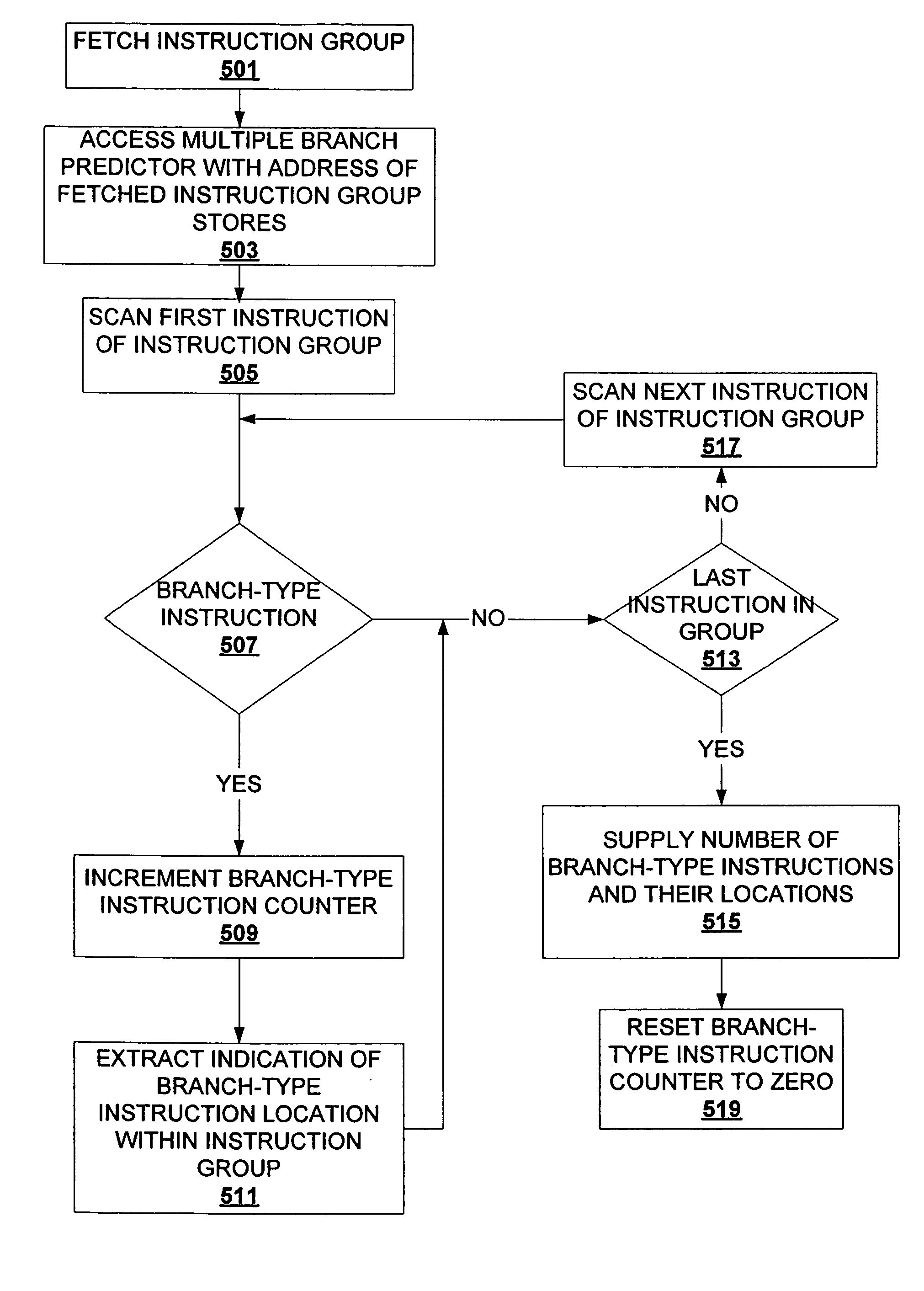
[0019] The description that follows includes exemplary systems, methods, techniques, instruction sequences and computer program products that embody techniques of the present invention. However, it is understood that the described invention may be practiced without these specific details. For instance, storing branch predictions for groups of instructions can be implemented with various data structures (e.g., hash tables, binary search trees, etc.) and/or with hardware mechanisms (e.g., hardware tables, content addressable memory, etc.). In other instances, well-known protocols, structures and techniques have not been shown in detail in order not to obscure the invention.
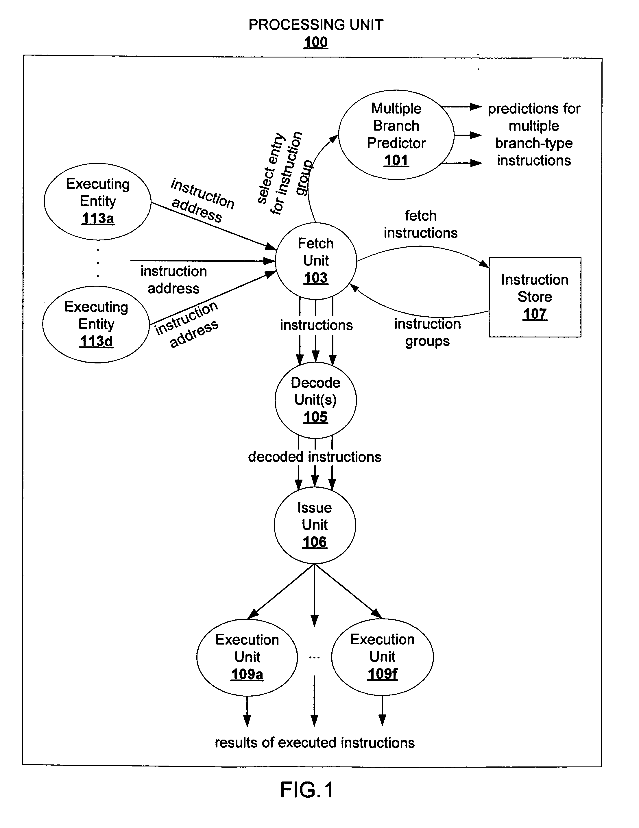
[0020] In particular, architecting a high performance processing environment that reconciles high frequency operation, pipeline processing environments with multiple threads, multiple cores, and/or multiple processors process instructions at a high rate. A high bandwidth pipeline for such processing environments is underutilized if the branch predictor lags behind the fetch and/or decode units.
[0021] High performance processing environments operate at high frequencies satisfying multiple threads, multiple cores, etc. To satisfy the constraints of space and demand for high performance, certain resources are duplicated while other resources are shared. To attain high pipeline bandwidth for high performance, a high performance processing unit includes multiple pipelines. However, multiple ones of the pipelines share resources, such as a fetch unit. Effective coordination between branch prediction, fetching and decoding facilitates efficient utilization of a high bandwidth pipeline. Efficient utilization of such a pipeline satisfies the performance demands of an environment with multiple concurrently executing entities (cores, processors, threads, etc.).
[0022] Coordination of multiple branch predictions with instruction fetching and decoding satisfies an aggressive processing environments, such as the aforementioned high performance processing environments. In addition, branch prediction reliability can be improved with branch prediction results of recent instructions. Conventional branch predictors utilize a branch history register, which is typically stale because of the latency between branch predictions and updating of the branch history register. Concurrently branch predicting for multiple branch-type instructions allows for instrumentation of branch predictions to allow for utilization of recent branch predictions while also satisfying high demand instruction pipeline environments.
[0023]FIG. 1 depicts an exemplary pipeline in an environment with multiple executing entities that supplies predictions for multiple branch-type instructions. A fetch unit 103 receives instruction addresses from executing entities 113a-113d. Exemplary executing entities 113a-113d include cores, processors, threads, etc. The fetch unit 103 fetches instructions from an instruction store 107 (e.g., an instruction cache), and receives groups of instructions. For example, the fetch unit 103 requests a line from the instruction store 107, and receives a group of instructions that are stored at the requested line. For each received instruction group, the fetch unit 103 accesses a multiple branch predictor 101. Branch prediction information for multiple instructions are supplied concurrently (e.g., at approximately the same time, such as within the same cycle, half cycle, etc.) from the multiple branch predictor 101. For example, the multiple branch predictor 101 may host branch prediction information for branch-type instructions of an instruction group and implicit or explicit indication that other instructions of an instruction group are not branch-type instructions. To illustrate, assume that a multiple branch predictor is organized into rows for each instruction group, and that each row includes 16 entries, corresponding to each instruction group having 16 instructions. The entries that correspond to branch-type instructions will indicate a prediction qualifier (e.g., a saturating counter that indicates branch prediction confidence, such as strongly taken, weakly taken, weakly not taken, strongly not taken). For those instruction groups that include multiple branch-type instructions, multiple branch predictions are concurrently supplied for the multiple branch-type instructions.
[0024] The fetched instructions are decoded by a decode unit(s) 105. The decoded instructions are then issued by an issue unit(s) 106. The issued instructions are then executed by execution units 109a-109f. The branch prediction information from the multiple branch predictor 101 may be supplied to one or more of the fetch unit 103, the decode unit(s) 105, the issue unit 106, and the execution units.
[0025]FIG. 2 depicts an exemplary out-of-order fetch unit. An out-of-order fetch unit 202 requests instructions at an address &A from an instruction store 205, at a time 1. The request misses in the instruction store 205. At a time 2, the instruction store 205 requests the instructions at &A from a memory 207 (e.g., L2 cache, L3 cache, system memory, etc.). The fetch unit 205 requests instructions at an address &B from the instruction store 205 and receives a corresponding instruction group, at a time 3. According to program order, the instructions at &A precede the instructions at &B. However, the fetch unit 201 stores the instruction group from &B in a fetch buffer 209b, at a time 4a. At a time 4b, the instruction store 205 receives the instruction group at &A from the memory 207. At a time 5, the instruction group at &A is stored in a fetch buffer 209b. A decode unit 211 decodes instructions stored in the fetch buffers 209a and 209b. The illustrated timing of these events is exemplary and may vary in realizations of the described invention. For example, the instruction groups may be requested concurrently, the instruction group at &A and the instruction group at &B may be received concurrently, the instruction group at &A may be received from the memory 207 prior to the fetch unit storing the instruction group at &B in the fetch buffer 209b, etc.
[0026] Even though the instruction groups at &A and &B are not available in accordance with program order, the fetch unit does not stall until it receives the instruction group at &A. Instead, the fetch unit 201 continues fetching instruction groups from the instruction store 205, regardless of program order. Hence, the unavailability of an instruction group in the instruction store does not ripple through the pipeline. When the instruction group at &A finally arrives and is available for decoding, subsequent instruction groups are readily available for the decode unit 211. Such utilization of a fetch unit allows for efficient utilization of an environment that shares fetch resources across multiple pipelines.
[0027]FIG. 3 depicts exemplary accessing of an exemplary multiple branch predictor. A fetch unit 301 accesses a multiple branch predictor 309 with an instruction group address and information about the instruction group. Exemplary information about the instruction group that flows from the fetch unit 301 to the multiple branch predictor 309 is depicted in FIG. 4. The multiple branch predictor 309 includes a branch prediction array 311, which includes branch prediction banks 303a-303f. Those of ordinary skill in the art will appreciate that the branch predictor can be implemented with a variety of techniques. For example, the branch prediction array may be implemented as a series of hardware tables, logical structures (e.g., hash tables, binary search trees, etc.) instantiated in memory, content addressable memory, etc. In addition, the functionality of the multiple branch predictor that accesses and selects branch prediction entries from the branch prediction array may be implemented with hardware (e.g., address lines, logic gates, etc.), software, a combination of hardware and software, etc.
[0028] In the illustrated example, the instruction group address flows into a hashing unit 305. For example, if a portion of an instruction's address (e.g., a program counter) indicates the address of the group that includes the relevant instruction (e.g., a certain number of most significant bits of a program counter), then that portion is supplied from the fetch unit 301. Branch history information from a branch history register(s) 307 also flows into the hashing unit 305. The hashing unit 305 hashes the branch history information with the instruction group address and generates an index into the branch prediction array 311. With the index, a plurality of branch prediction entries are selected in each of the branch prediction banks 303a-303f. Various realizations of the described invention access branch prediction information with different techniques (e.g., a hash of the instruction group address without the branch history, the instruction group address without hashing, etc.). Each entry selected from a bank provides branch prediction information at instruction group granularity. Additional information is garnered (in parallel or prior to selection from the banks), to further filter the selected instruction group branch predictions.
[0029]FIG. 4 depicts exemplary scanning of an instruction group. A fetch unit 401 includes an instruction group scan unit 403. The instruction group scan unit 403 scans an instruction group 405. For example, the instruction group scan logic 403 scans the opcode of each instruction within the instruction group 405. From the scanning, the instruction group scan unit 403 can determine a variety of information about the instruction group useful for processing the instructions of the instruction group. In FIG. 4, the instruction group scan unit 403 determines the number of branch-type instructions in the instruction group 405, and the locations of the branch-type instructions in the instruction group 405. In FIG. 4, the instruction group scan unit 403 supplies an indication of the number of branch-type instructions, and locations of a first and a second branch-type instruction. This information is supplied from the fetch unit 401 to a multiple branch predictor, such as the multiple branch predictor 101 of FIG. 1 or the multiple branch predictor 309 of FIG. 3.
[0030]FIG. 5 depicts an exemplary flowchart for fetching and scanning instructions. At block 501, an instruction group is fetched. At block 503, a multiple branch predictor is accessed with an address of the fetched instruction group. At block 505, the first instruction of the fetched instruction group is scanned. At block 507, it is determined if the scanned instruction is a branch-type instruction. If the scanned instruction is a branch-type instruction, then control flows to block 509. If the scanned instruction is not a branch-type instruction, then control flows to block 513.
[0031] At block 509, a branch-type instruction counter is incremented. At block 511, an indication of location of the branch-type instruction within the instruction group is extracted. Control flows from block 511 to block 513.
[0032] At block 513, it is determined if the scanned instruction is the last instruction of the instruction group. If the scanned instruction is not the last instruction of the instruction group, then control flows to block 517. If the scanned instruction is the last instruction of the instruction group, then control flows to block 515.
[0033] At block 517, the next instruction of the instruction group is scanned. From block 517, control flows to block 507.
[0034] At block 515, the number of branch-type instructions and their locations (if any) are supplied. At block 519, the branch-type instruction counter is reset to zero.
[0035]FIG. 6 depicts an exemplary multiple branch predictor. A multiple branch predictor 600 includes branch prediction banks 603a-603e, various select elements (e.g., multiplexers), a store element 625 for a previous instruction group branch prediction state, and an instruction group branch prediction states unit 623. The organization of the elements of the exemplary multiple branch predictor 601 is illustrated to aid in understanding the described invention and not meant to limit the described invention. For example, the individual branch prediction banks may be distinct from each other, a single contiguous store element with multiple access ports, etc. One of ordinary skill in the art will appreciate the various sizes of data in FIG. 6 are provided for illustrative purposes alone, and that various realizations of the described invention may implement instructions of various sizes, instruction group branch prediction states of various sizes, branch predictions of various sizes, etc. The branch prediction banks 603a-603e are accessed in accordance with an index that corresponds to a current instruction group. A plurality of branch prediction entries (e.g., a row of branch predictions) is selected from each of the branch prediction banks 603a-603e. The branch predictions entries from each of the branch prediction banks 603a-603e flow into a select element 609. In FIG. 6, each row of a branch prediction bank corresponds to an instruction group. Each entry of each row corresponds to an instruction of an instruction group. The select element 609 receives a control signal from a store element 625 which controls which of the branch prediction banks 603a-603e will be selected. The store element 625 hosts a previous instruction group branch prediction states, which is stored in the store element 625 from an instruction group branch prediction states unit 623, which will be described in more detail below. Various realizations of the described invention implement deterministic techniques to drive selection of the select element 609 and avoid non-deterministic selection of branch predictions. For example, information may be utilized to weigh selection of the branch prediction banks in accordance with observed behavior (e.g., the modulus of the previous instruction group branch prediction state indication is used to select a branch prediction bank). Hence, selection of the branch prediction banks is determinative and not random. The determinative aspect allows reliance on consistency. Thus, when looping back through a same piece of code, the branch prediction should be consistent and not vary in relation to processing factors, such as load on a shared fetch unit.
[0036] After the desired branch prediction bank is selected, the row of the selected branch prediction bank flows into select elements 611 and 613. The select element 611 receives as control input the location of a first branch-type instruction within the current instruction group. The prediction information for the first branch-type instruction of the current instruction group is selected and is supplied for further processing of the corresponding branch-type instruction. Likewise, the select element 613 receives as control input the location of a second branch-type instruction within the current instruction group. The prediction information for the second branch-type instruction of the current instruction group is selected accordingly and supplied for further processing of the second branch-type instruction, if applicable.
[0037] The portion of the prediction information that indicates whether the branch of the corresponding branch-type instruction is taken or not taken is pulled and forwarded to the instruction group branch prediction states unit 623. In the exemplary illustration of FIG. 6, the most significant bit of 2-bit branch predictions is pulled.
[0038] The instruction group branch prediction states unit 623 stores indications of 5 possible branch prediction states for an instruction group. In the exemplary illustration of FIG. 6A, the multiple branch predictor 600 is implemented for generating branch predictions for 2 branch-type instructions in an instruction group. Various realizations of the described invention may implement a multiple branch predictor that concurrently branch predicts for a fewer or greater number of branch-type instructions, and implement the number of branch prediction banks, which correspond to the instruction group branch prediction states, and the instruction group branch prediction states unit 623 accordingly. In FIG. 6, the instruction group branch prediction states unit 623 indicates the following instruction group branch prediction states: no branches (there were no branch-type instructions within the instruction group); 1 taken (there was one branch-type instruction and it was predicted taken); 1 not taken (there was one branch-type instruction and it was predicted not taken); 1 not taken, then 1 taken (there were at least two branch-type instructions, the first was predicted not taken and the second was predicted taken); and 2 not taken (there were 2 branch-type instructions and both were predicted not taken). There are more possible instruction group branch prediction states (e.g., 2 taken), but they can be decomposed into the preceding instruction group branch prediction states. The branch predictions for the current instruction group along with the number of branch-type instructions in the current instruction group are input into the instruction group branch prediction states unit 623. The appropriate instruction group branch prediction state indication is selected and stored in the store element 625. This stored instruction group branch prediction state serves as the previous instruction group branch prediction state for the next instruction group.
[0039] Assume that branch prediction in accordance with FIG. 6 occurs over three pipeline stages and that a fetch unit is shared between two pipelines. In a first stage (F1) an instruction store (e.g., instruction store 107 or 205) is accessed to fetch a first instruction group that includes one or more branch-type instructions for a first pipeline. A branch prediction array, such as the branch prediction array 311 of FIG. 3, is also accessed in stage F1 to retrieve branch predictions for the first fetched instruction group. After the first instruction group is fetched, the shared fetch unit fetches for a second pipeline. When the fetch unit returns to the first pipeline, the instruction store is accessed to fetch a second instruction group for the first pipeline, as well as the branch prediction array being accessed for the second instruction group. The delay introduced by the fetch unit fetching for another pipeline, as well as the selection of the multiple possible branch predictions for the second instruction group, allows the branch predictions for the first instruction group to be available for branch prediction of the second instruction group. Hence, the combination of the alternation between pipeline by the shared fetch unit and the selection of multiple candidate branch prediction prior to selection of the actual branch prediction, synchronizes the branch prediction fetching in the high performance processing environment and avoids the branch predictor from lagging behind.
[0040] The above example is provided to aid in understanding the described invention and not meant to be limiting upon the invention. Deterministic branch prediction for multiple branches can be implemented regardless of the number of pipelines. Regardless of technique or environment, a preceding branch prediction is available after selection of multiple entries from the branch prediction array, and the eventual selection of the appropriate branch predictions taking into consideration the preceding branch prediction. To avoid non-deterministic branch prediction, the branch history register does not include the preceding branch prediction. A mechanism separate from the branch history register (as illustrated in FIG. 5) supplies the branch prediction for a preceding branch type instruction or group of branch type instructions. Hence, a single pipeline can also utilize a mechanism to provide deterministic branch prediction for multiple branch type instructions (e.g., serve other threads while the branch predictions are being read from a branch prediction array, sleep for a given amount of time while the branch predictions are being read from a branch prediction array, etc.).
[0041]FIG. 7 depicts exemplary updating of a branch prediction array 701. At an execution stage, branch-type instructions are resolved. The resolution of the branch-type instructions are sent to the branch prediction array 701 along with additional information for locating the appropriate one or more entries. The address of the resolved branch-type instruction is supplied from the execution stage back to the branch prediction array 701 in the fetch stage. The address of the branch-type instruction (e.g., the program counter) and the relevant instruction group branch prediction state are utilized to update the branch prediction array 701 with the branch-type instruction resolution.
[0042]FIG. 8 depicts an exemplary flowchart for updating a branch prediction array. At block 801, a branch-type instruction is resolved. At block 803, an indication of the instruction group is extracted from the branch-type instruction (e.g., certain number of most significant bits of the program counter) and the indicated instruction group is requested from memory (e.g., the instruction group is retrieved from cache). At block 805, a row is selected from all banks in accordance with the extracted instruction group indication (i.e., the same row is selected across all banks). At block 807, a corresponding previous instruction group branch prediction state is retrieved. Various realizations of the described invention implement techniques for locating the appropriate entry in a branch prediction array for updating. For example, a separate data structure is maintained to track branch predictions that have not been verified. In another example, the branch-type instructions are tagged with location information. Tagging branch-type instructions would not add overhead since the instruction store accommodates sufficient space for instruction types that require more information than a branch-type instruction. Hence, an entry in an instruction store has space sufficient for the branch-type instruction and one or more tags. At block 809, a branch prediction bank is selected according to the retrieved corresponding previous instruction group branch prediction state. At block 811, assuming sufficient time has passed for the requested instruction group to be retrieved from memory, an indication of the location of the branch type instruction(s) within the instruction group is extracted. At block 813, from the selected row of the selected bank, a branch prediction entry is selected in accordance with the extracted location indication. At block 815, the selected entry is updated in accordance with the branch resolution.
[0043] While the flow diagram shows a particular order of operations performed by certain realizations of the invention, it should be understood that such order is exemplary (e.g., alternative realizations may perform the operations in a different order, combine certain operations, overlap certain operations, perform certain operations in parallel, etc.). For example, block 503 may be performed in parallel with block 505-517; blocks 505-517 maybe performed before block 503; etc.
[0044] The described invention may be provided as a computer program product, or software, that may include a machine-readable medium having stored thereon instructions, which may be used to program a computer system (or other electronic devices) to perform a process according to the present invention. A machine readable medium includes any mechanism for storing or transmitting information in a form (e.g., software, processing application) readable by a machine (e.g., a computer). The machine-readable medium may include, but is not limited to, magnetic storage medium (e.g., floppy diskette); optical storage medium (e.g., CD-ROM); magneto-optical storage medium; read only memory (ROM); random access memory (RAM); erasable programmable memory (e.g., EPROM and EEPROM); flash memory; electrical, optical, acoustical or other form of propagated signal (e.g., carrier waves, infrared signals, digital signals, etc.); or other types of medium suitable for storing electronic instructions.
[0045]FIG. 9 depicts an exemplary computer system according to realizations of the invention. A computer system 900 includes a processor unit 901 (possibly including multiple processors, a single threaded processor, a multi-threaded processor, a multi-core processor, etc.). The computer system 900 also includes a system memory 907A-907F (e.g., one or more of cache, SRAM DRAM, RDRAM, EDO RAM, DDR RAM, EEPROM, etc.), a system bus 903 (e.g., LDT, PCI, ISA, etc.), a network interface 905 (e.g., an ATM interface, an Ethernet interface, a Frame Relay interface, etc.), and a storage device(s) 909A-909D (e.g., optical storage, magnetic storage, etc.). Realizations of the invention may include fewer or additional components not illustrated in FIG. 9 (e.g., video cards, audio cards, additional network interfaces, peripheral devices, etc.). The processor unit 901, the storage device(s) 909A-909D, the network interface 905, and the system memory 907A-907F are coupled to the system bus 903. The processor unit 901 includes a multiple branch predictor that concurrently branch predicts for multiple branch-type instructions and an out-of-order fetch unit.
[0046] While the invention has been described with reference to various realizations, it will be understood that these realizations are illustrative and that the scope of the invention is not limited to them. Many variations, modifications, additions, and improvements are possible. More generally, realizations in accordance with the present invention have been described in the context of particular realizations. For example, the blocks and logic units identified in the description are for understanding the described invention and not meant to limit the described invention. Functionality may be separated or combined in blocks differently in various realizations of the invention or described with different terminology. For example, an operation fetch unit may be referred to as an instruction fetch unit, an instruction buffer may perform some or all of the functionality of the operation fetch unit, the operation scheduling unit, and/or the renaming unit, the memory disambiguation buffer may be referred to as a data hazard resolution unit, the memory disambiguation buffer may include a data hazard resolution unit, etc.
[0047] These realizations are meant to be illustrative and not limiting. Accordingly, plural instances may be provided for components described herein as a single instance. Boundaries between various components, operations and data stores are somewhat arbitrary, and particular operations are illustrated in the context of specific illustrative configurations. Other allocations of functionality are envisioned and may fall within the scope of claims that follow. Finally, structures and functionality presented as discrete components in the exemplary configurations may be implemented as a combined structure or component. These and other variations, modifications, additions, and improvements may fall within the scope of the invention as defined in the claims that follow.

PUM

no PUM

Description & Claims & Application Information

We can also present the details of the Description, Claims and Application information to help users get a comprehensive understanding of the technical details of the patent, such as background art, summary of invention, brief description of drawings, description of embodiments, and other original content. On the other hand, users can also determine the specific scope of protection of the technology through the list of claims; as well as understand the changes in the life cycle of the technology with the presentation of the patent timeline. Login to view more.

Similar technology patents

Classification and recommendation of technical efficacy words

  • Improve reliability
  • Facilitate availability

Arc-shaped cutting anastomat

ActiveCN101912284AGood assembly firmnessImprove reliabilitySurgical staplesDistal anastomosisEngineering
Owner:CHANGZHOU JIANRUIBAO MEDICAL DEVICES

Distributed power harvesting systems using DC power sources

ActiveUS20080143188A1Improve reliabilitySafe operating voltageDc network circuit arrangementsBatteries circuit arrangementsTransverterVoltage variation
Owner:SOLAREDGE TECH LTD
Why Eureka
Try Eureka