Alien fall arrest safety system
a safety system and technology of aliens, applied in safety belts, sports equipment, cleaning equipment, etc., can solve the problems of increased labor costs, increased time spent on site, and increased risk of incorrect installation,
- Summary
- Abstract
- Description
- Claims
- Application Information
AI Technical Summary
Benefits of technology
Problems solved by technology
Method used
Image

Examples
first embodiment
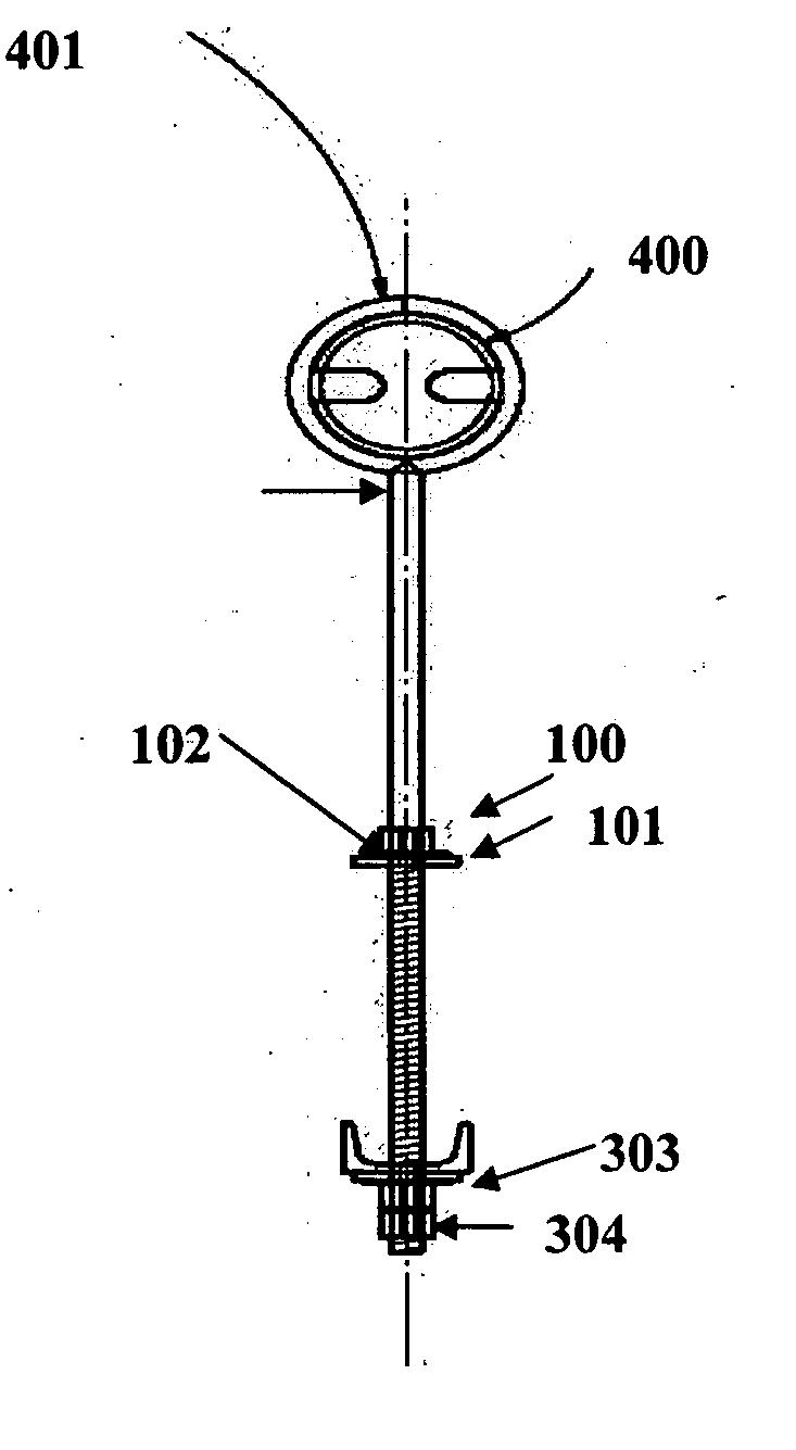
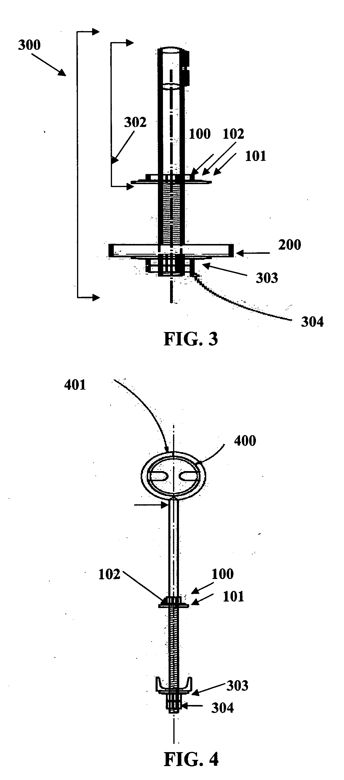
[0045] With respect to FIG. 1 through 4, the stainless steel rod 300 of the first embodiment, known as Alien and depicted in FIGS. 3 and 4, is approximately ¾-inch in diameter and approximately 2-feet 6 inches in length. The mechanism for attachment of the safety line consists of an approximate 5½ inch diameter ring 401, as can be seen in FIG. 4, formed at the top of the energy absorption mast 302 from the proximal portion of rod 300 and welded to close the ring 401 formed and create an eye bolt of approximately 2 feet and ¼ inches in length. The preferred material used to form the eye bolt is stainless steel; however other materials may be used in accordance with the present invention. The circular plate 400 has two slots, each roughly in the shape of a letter “u” oriented horizontally. The assembly of the slotted circular plate 400 over ring 401 provides for two locations where a safety harness clip may be secured.
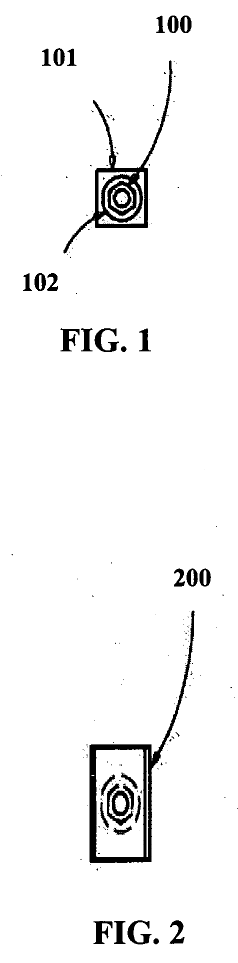
[0046] The upper assembly components, depicted in FIG. 1 and assemb...
second embodiment
[0048] The stainless steel rod 300 of the present invention, known as Alien SS (FIGS. 5 through 9), is approximately ⅞ inch in diameter stainless steel and is approximately 2 feet 6 inches in length. The mechanism for attachment of the safety line consists of an approximate 5½ inch diameter circular ring 401 formed out of the proximal portion of the rod 300. The end of the formed ring 401 is welded to the main rod 300 to create a joint, leaving an approximate 2 feet and ¼ inch of substantially straight length remaining in the rod 300. The face of the ring 401 is covered with an approximately 1 / 8 inch thick circular plate 401, illustrated in FIG. 7, made of stainless steel. The circular plate 400 has two slots, each roughly in the shape of a letter “u” oriented horizontally. The assembly of the slotted circular plate 400 over the ring 401 provides for two locations where a safety harness clip may be secured.
[0049] The upper assembly components in the Alien SS system consist of a jack...
third embodiment
[0054] The galvanized bolt 1304 of the present invention, known as Street Alien (illustrated in FIGS. 10 through 14), is approximately 7 / 8 inch in diameter bolt and is approximately 2 feet 3 inches in length. The mechanism for attachment of the safety line consists of an approximately ½ inch thick rectangular plate 1200 with an area of 12×6 inches,) preferably manufactured of grade A36 steel. This plate is welded horizontally to the top of a jacket sub-assembly 1300 described below. The rectangular plate 1200 has a centrally located 15 / 16 inch diameter hole 1201 for assembly of the galvanized bolt 1304. Additionally, the rectangular plate 1200 has two 15 / 16 inch diameter holes 1202, each located a 5 inches from either side of the central hole 1201, near the ends of the plate. These holes 1202 are intended to provide a plurality of locations for attachment of safety harness clips.
[0055]FIGS. 13 and 14 show the upper assembly components in the Street Alien system of the present invent...
PUM
 Abstract
Description
Claims
Application Information
 - R&D
- Intellectual Property
- Life Sciences
- Materials
- Tech Scout
- Unparalleled Data Quality
- Higher Quality Content
- 60% Fewer Hallucinations
Browse by: Latest US Patents, China's latest patents, Technical Efficacy Thesaurus, Application Domain, Technology Topic, Popular Technical Reports.
© 2025 PatSnap. All rights reserved.Legal|Privacy policy|Modern Slavery Act Transparency Statement|Sitemap|About US| Contact US: help@patsnap.com