Method for reducing resistance of flying object using expandable nose cone

a technology of expanding cone and flying object, which is applied in the direction of fuselage, weapons, projectiles, etc., can solve the problems of reducing the resistance of flying objects, reducing the volume efficiency of flying objects, and reducing the air resistance, so as to reduce the air resistance even more significantly, increase the volume efficiency, and reduce the resistance

Inactive Publication Date: 2005-12-08
JAPAN AEROSPACE EXPLORATION AGENCY
View PDF11 Cites 4 Cited by
  • Summary
  • Abstract
  • Description
  • Claims
  • Application Information

AI Technical Summary

Benefits of technology

[0006] The aim of the present invention is to provide a flying object using a thin elongated nose cone with a small tip angle for reducing the air resistance during flying, where the maximum loading capacity can be increased without decreasing the volume efficiency of the flying object by limitations placed on the accommodation space, regardless of the structure thereof.
[0007] In the flying object in accordance with the present invention, which comprises a nose cone in the tip portion, the nose cone portion has a structure that is compressed in the axial direction during accommodation and expands on the tip side in the axial direction during flying, due to an expandable nose cone structure such that a disk with a small diameter is disposed in the forward position and the disks with a successively increasing diameter are disposed in the axial direction. At the time of accommodation in a fuselage, the nose cone is compressed in the axial direction and the volume efficiency is increased. After separation, the nose cone expands in the axial direction, deep cavities are formed between the disks, a fine elongated nose cone with a small tip angle is provided, and the air resistance is reduced.
[0008] In the flying object in accordance with the present invention, which comprises a nose cone in the tip portion, a member of a conical shape is disposed in the tip of the nose cone to decrease the air resistance even more significantly.
[0009] In the flying object in accordance with the present invention, which comprises a nose cone in the tip portion, a mechanism is provided that employs, for example, a telescopic pole and enables the variation of the axial length of the nose cone.
[0010] In the flying object in accordance with the present invention, which comprises a nose cone in the tip portion, the expandable nose cone is constructed so as to have a structure such that a disk with a small diameter is disposed in the forward position and the disks with a successively increasing diameter are disposed in the axial direction. As a result, volume efficiency during flying object accommodation is improved, a fine elongated nose cone is obtained which expands in the axial direction after separation, the air resistance after flying object separation is reduced, and the increase in the continuous flying distance can be expected.
[0012] In the flying object in accordance with the present invention, which comprises a nose cone in the tip portion, a mechanism is provided that employs, for example, a telescopic pole and enables the variation of the axial length of the nose cone. Therefore, switching operations of compacting the shape of the nose cone portion during accommodation and extending it in the axial direction after separation are conducted reliably and rapidly.

Problems solved by technology

However, the problem associated with thin elongated nose cones was that under conditions of limited accommodation space, the length of the main body had to be reduced which resulted in a decreased volume efficiency of the flying object and placed a limitation on the maximum load capacity thereof.
The aim of this invention is to reduce the resistance during flying and to obtain good aerodynamic characteristic, but it relates to a rudder wing and does not improve the tip of the flying object.

Method used


Image

  • Method for reducing resistance of flying object using expandable nose cone
  • Method for reducing resistance of flying object using expandable nose cone
  • Method for reducing resistance of flying object using expandable nose cone

Examples


embodiment 1

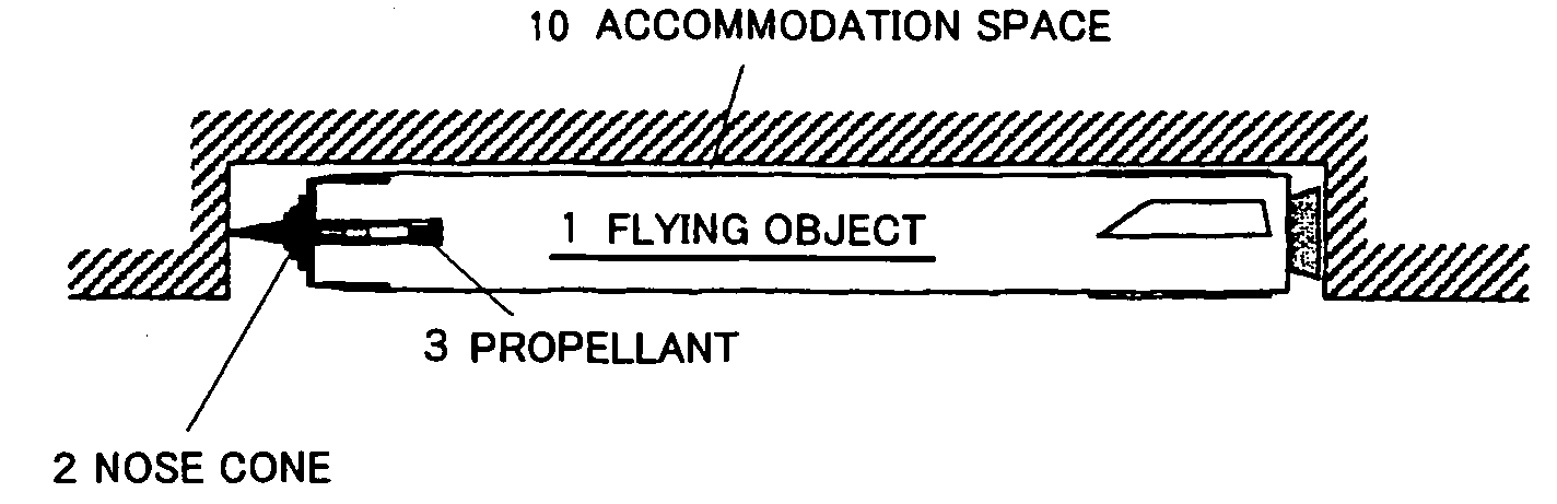
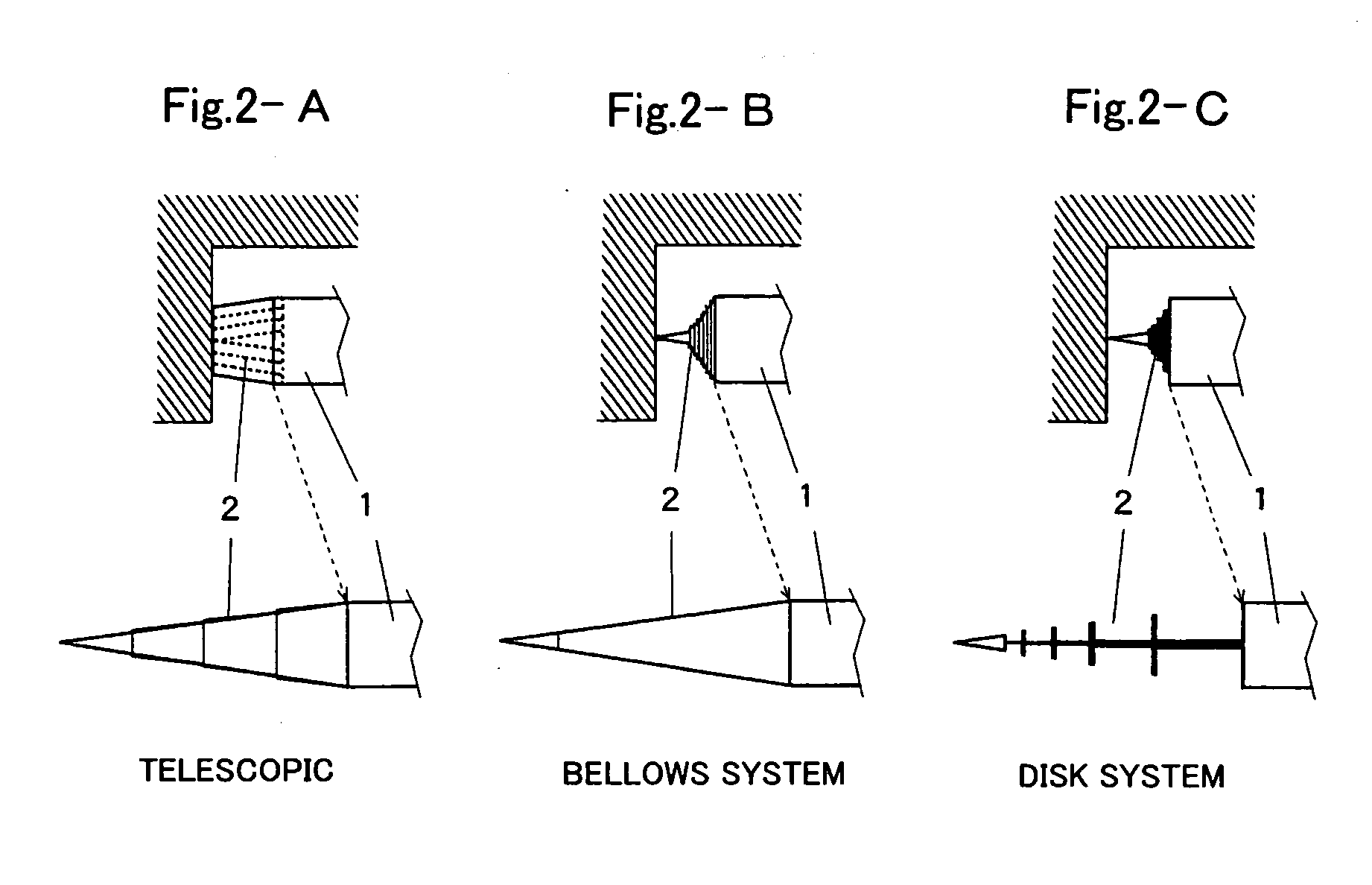
[0029] One embodiment of the disk system will be described based on the above-described data with reference to FIG. 7. In this embodiment, an expandable nose cone was constructed by using three disks and a tip cone. FIG. 7A shows an accommodation state of a flying object 1, wherein part of a nose cone 2 is in a compressed state inside an accommodation space 10. FIG. 7B shows a state in which the flying object was separated from the accommodation portion and the nose cone 2 has expanded and started flying. Further, FIG. 7C is an enlarged view of the expanded nose cone portion. The three disks 2b and tip cone member 2a, which constitute the nose cone 2, are fixed to the tips of respective shafts 2c, the shafts 2c are so formed that the diameter thereof decreases toward the tip side, and the shafts 2c are in the form of the so-called telescopic pole in which each next member is accommodated inside the previous one. The nose cone 2 in which the tip cone member 2a and the disks 2b are in...


PUM


Abstract

It is an object of the present invention to provide a flying object using a thin elongated nose cone with a small tip angle for reducing the air resistance during flying, wherein the maximum loading capacity can be increased without decreasing the volume efficiency of the flying object by limitations placed on the accommodation space, regardless of the structure thereof. In the flying object in accordance with the present invention, which comprises a nose cone in the tip portion, the nose cone portion has a compressed structure in the axial direction during accommodation and expands on the tip side in the axial direction during flying, due to an expandable nose cone structure such that a disk with a small diameter is disposed in the forward position and the disks with a successively increasing diameter are disposed in the axial direction. After separation, the nose cone expands in the axial direction, deep cavities are formed between the disks, and a fine elongated nose cone with a small tip angle is provided, whereby the air resistance is reduced.

Description

BACKGROUND OF THE INVENTION [0001] 1. Field of the Invention [0002] The present invention relates to a method for reducing the resistance of a flying object that is carried by an aircraft or the like and is separated therefrom in the air. [0003] 2. Description of the Related Art [0004] Forming the tip portion of a flying object as a thin elongated nose cone with a small tip angle is effective for reducing the air resistance of the flying object. However, the problem associated with thin elongated nose cones was that under conditions of limited accommodation space, the length of the main body had to be reduced which resulted in a decreased volume efficiency of the flying object and placed a limitation on the maximum load capacity thereof. Attempts to obtain a compact structure in the accommodation state by using a partially folded structure of the flying object in order to make the shape of the flying object as small as possible due to limited space for accommodating the flying objec...

Claims


Application Information

Patent Timeline
Patent Type & Authority Applications(United States)
IPC IPC(8): F42B10/46F42B12/10
CPCF42B12/105F42B10/46
Inventor KOBAYASHI, HIROAKITANATSUGU, NOBUHIROSATO, TETSUYAHONGO, MOTOYUKIMARU, YUSUKE
Owner JAPAN AEROSPACE EXPLORATION AGENCY
Why Eureka
Try Eureka