
Color picture tube

a color picture and tube technology, applied in the field of color picture tubes, can solve the problems of affecting the appearance of the tube, the amount of the landing position shift of the electron beam, and the remarkably low cost of alloys, so as to achieve satisfactory moldability, less color purity degradation, and good moldability

Inactive Publication Date: 2005-12-08
MATSUSHITA TOSHIBA PICTURE DISPLAY CO LTD
View PDF12 Cites 87 Cited by
  • Summary
  • Abstract
  • Description
  • Claims
  • Application Information

AI Technical Summary

Benefits of technology

[0018] Therefore, with the foregoing in mind, it is an object of the present invention to provide a color picture tube that has satisfactory visibility, and less degradation in color purity caused by doming while having a shadow mask made of an inexpensive material with satisfactory moldability.

Problems solved by technology

Therefore, the amount of the landing positional shift of the electron beams also increases, and the color purity degrades remarkably.
Such an alloy entails high cost, while having a coefficient of thermal expansion of 1 to 2×10⁻⁶ at 0° C. to 100° C., and being effective for suppressing doming.
Furthermore, the iron-nickel alloy has large elasticity after annealing, so that it is difficult to form a curved surface from such an alloy by molding and to obtain a desired curved surface.
Particularly, in a color picture tube with a flat panel outer surface, the curvature of the shadow mask 7 is small, so that molding is further difficult.
In the case where molding is insufficient, and undesired stress remains in the shadow mask 7 after molding, the residual stress changes the shape of the shadow mask 7 in the course of production of the color picture tube, which leads to the landing positional shift of the electron beams, resulting in the significant degradation in color purity.
, which is disadvantageous for doming. P
articularly, in the case of applying such a material to a color picture tube in which the outer surface of the useful surface 1 of the panel 3 is substantially flat, there arises a serious problem such as the significant degradation in color purity.
However, in the case of using an inexpensive iron material, a sufficient effect cannot be obtained.
However, in this cathode-ray tube, a sufficient effect of suppressing doming cannot be obtained, either, in the same way as in JP 10(1998)-199436 A. When an attempt is made to obtain a sufficient effect of suppressing doming, the weight of a panel increases, compared with the case of using an expensive Invar material.
On the other than, when an inexpensive iron material with satisfactory moldability is used, the landing positional shift of the electron beams occurs due to the local doming of the shadow mask 7 during an operation of a color picture tube, causing a phosphor other than the phosphors, which are supposed to emit light, to emit light, resulting in the degradation in color purity of the color picture tube.

Method used


Image

  • Color picture tube
  • Color picture tube
  • Color picture tube

Examples


embodiment 1

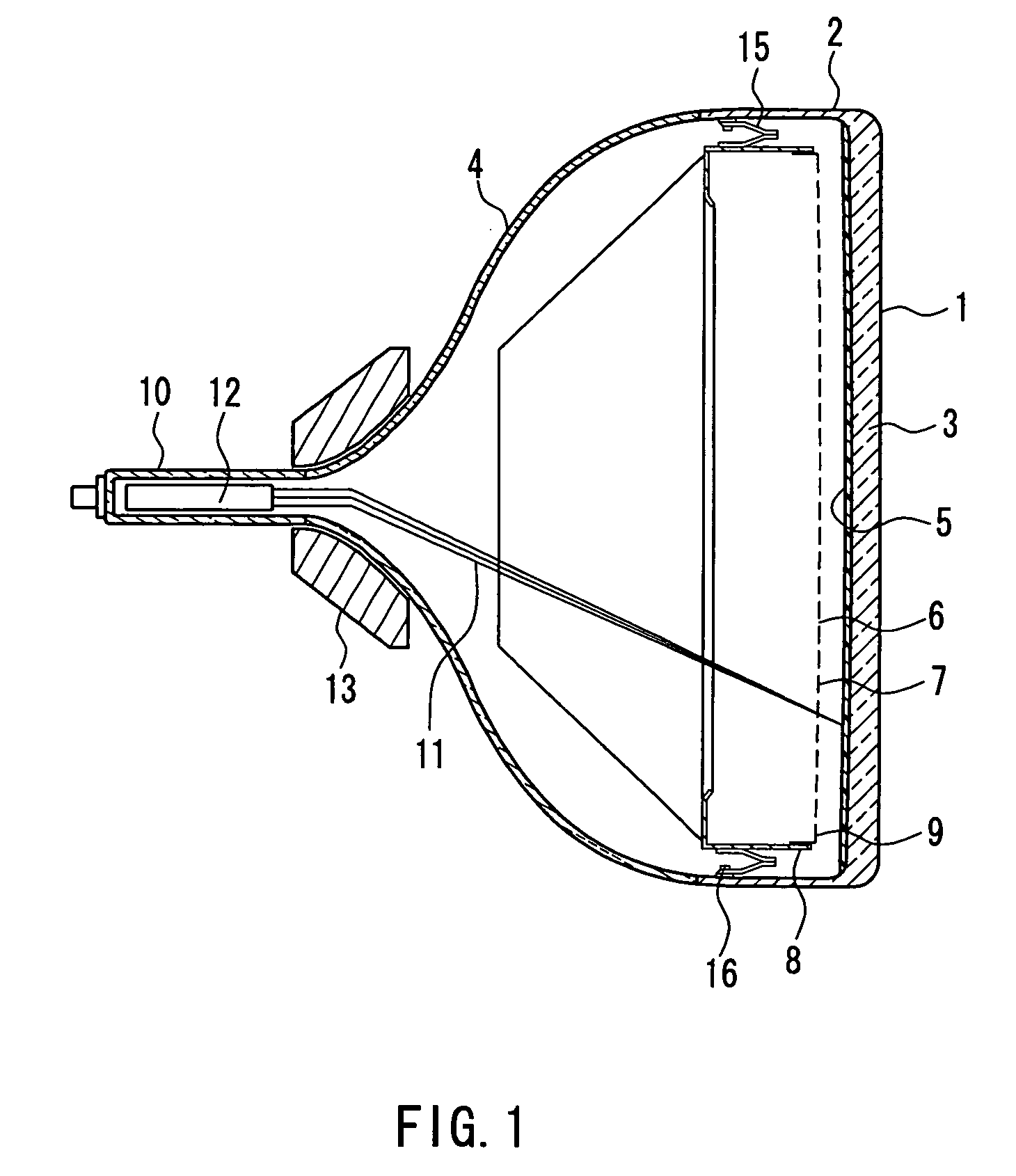
[0042]FIG. 1 is a cross-sectional view of a color picture tube. The color picture tube includes an envelope composed of a substantially rectangular panel 3 in which a skirt portion 2 is provided on the periphery of an useful surface 1 on which an image is displayed, and a funnel 4 in a funnel shape connected to the skirt portion 2. A substantially rectangular shadow mask 7 having a curved surface in which a number of electron beam passage apertures 6 are formed is placed so as to be opposed to a phosphor screen 5 made of three-color phosphor layers formed on an inner surface of the useful surface 1 of the panel 3. The shadow mask 7 is held by a substantially rectangular mask frame 8 having a substantially L-shaped cross-section. A shadow mask structure 9 composed of the shadow mask 7 and the mask frame 8 is supported detachably with respect to the panel 3 with one end of a substantially V-shaped elastic support 15 attached to each corner portion or respectively on a short side and a...

embodiment 2

[0091] In a color picture tube, it is preferable that the interval q between the panel 3 and the shadow mask 7 is set appropriately over an entire range of a screen. Therefore, it is preferable that the inner surface of the panel 3 has a curvature close to that of the curved surface of the shadow mask 7. In the case where the shadow mask 7 is made of a material containing 95% or more of iron, and the surface thereof is set in a shape effective for suppressing doming, as described in Embodiment 1, it is preferable that the inner surface of the panel 3 satisfies the conditions similar to those in Embodiment 1. The reason for this is as follows.

[0092] The phosphor screen 5 is formed by a light-exposure method using the shadow mask 7 as a mask. More specifically, as shown in FIG. 10, phosphor stripes of three colors (red, green, and blue) are obtained by irradiating the inner surface of the panel 3 with light beams from light sources 18R, 18G, and 18B of a light-exposure apparatus, app...


PUM


Abstract

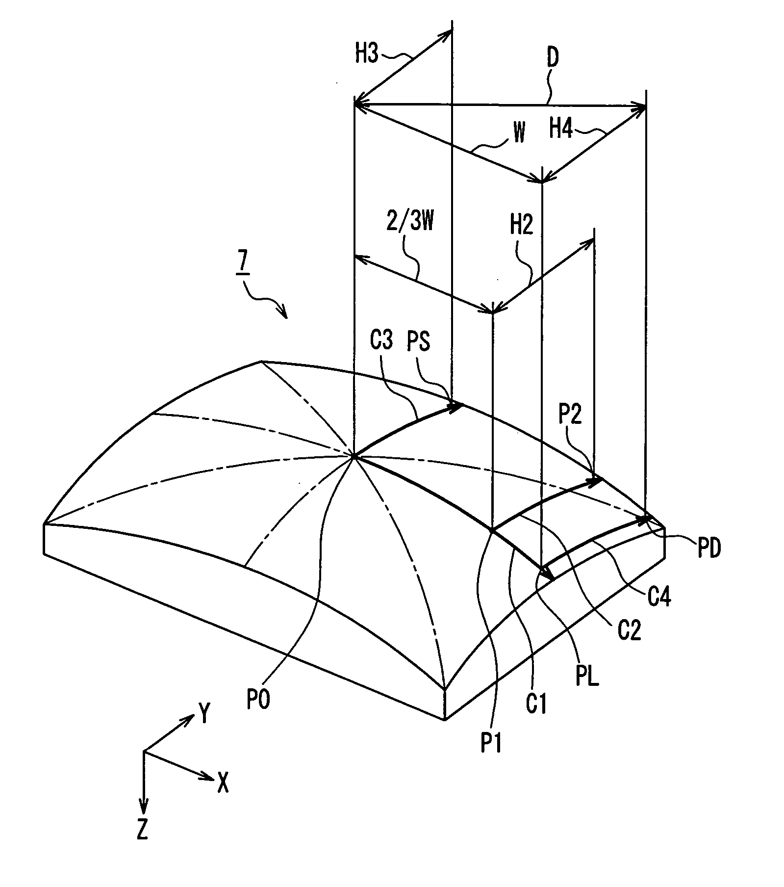
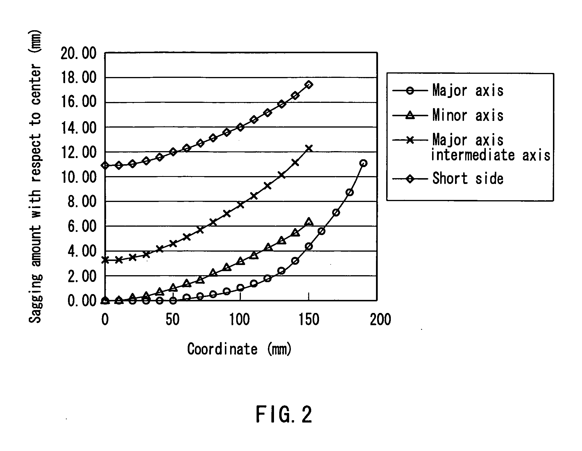
The radius of curvature of the outer surface of a panel is 10,000 mm or more, and a shadow mask is made of a material containing 95% or more of iron. A sagging amount change curve along a curve C1 on the surface of the shadow mask, which a plane passing through a center P0 of a useful area of the shadow mask and parallel to a tube axis and a major axis crosses, satisfies a particular Condition 1. Assuming that an intersection between the curve C1 and a useful area end of the shadow mask is a major axis end PL, a distance from the center P0 to the major axis end PL along a major axis is W, and a point on the curve C1 away from the center P0 by ⅔×W in the major axis direction is P1, a sagging amount change curve along a curve C2 on the surface of the shadow mask, which a plane passing through the point P1 and parallel to the tube axis and the minor axis crosses, satisfies a particular Condition 2. Consequently, a color picture tube can be realized, which has satisfactory visibility, and less degradation in color purity caused by doming while having a shadow mask made of an inexpensive material with satisfactory moldability.

Description

BACKGROUND OF THE INVENTION [0001] 1. Field of the Invention [0002] The present invention relates to a color picture tube provided with a shadow mask. [0003] 2. Description of the Related Art [0004] In general, as shown in FIG. 1, a color picture tube includes an envelope composed of a substantially rectangular panel 3 in which a skirt portion 2 is provided on the periphery of a useful surface 1 formed of a curved surface, and a funnel 4 in a funnel shape connected to the skirt portion 2. A substantially rectangular shadow mask 7 having a curved surface, in which a number of electron beam passage apertures 6 are formed, is placed so as to be opposed to a phosphor screen 5 composed of three-color phosphor layers formed on an inner surface of the useful surface 1 of the panel 3. The shadow mask 7 is held by a substantially rectangular mask frame 8. A shadow mask structure 9 composed of the shadow mask 7 and the mask frame 8 is supported detachably with respect to the panel 3 with one ...

Claims


Application Information

Patent Timeline
IPC IPC(8): H01J29/07H01J29/80H01J29/86
CPCH01J29/07H01J29/861H01J2229/862H01J2229/0794H01J2229/0788
Inventor SHIMIZU, NORIONIHEI, FUMIAKIUCHIKAWA, TOSHIO
Owner MATSUSHITA TOSHIBA PICTURE DISPLAY CO LTD
Learn More