Reflective liquid crystal display device and reflective liquid crystal display device incorporating touch panel arranged therefrom

Inactive Publication Date: 2005-04-14
SHARP KK
View PDF3 Cites 6 Cited by
  • Summary
  • Abstract
  • Description
  • Claims
  • Application Information

AI Technical Summary

Benefits of technology

The present invention has objects to solve the aforementioned problems in a reflective liquid crystal display device of a single polarizer plate mode which can realize a high resolution display, and thereby to offer a reflective liquid crystal display device that boasts excellent visibility with a high contrast

Problems solved by technology

In addition, as to display contrast properties, the light emitting display device, such as the CRT, degrades greatly in contrast ratio when used outdoors during the daytime.
Even the transmissive liquid crystal display device subjected to a low reflection treatment inevitably suffers similarly from greatly decreased contrast ratios when used in ambient light, such as direct sunlight, that is excessively strong compared to display light.
When considering these potential application fields, the reflective color liquid crystal display device appears very promising; however, a relatively low contrast ratio and reflectance, as well as insufficient performances in multi-color, high precision, and moving picture display, have so far been obstacles in realizing commercially viable reflective color liquid crystal display device.
This causes moire and other undesirable phenomena, rendering the transmissive liquid crystal display device unsuited for high resolution, high precision, color display use.
For these reasons, no reflective color display device using this display mode has so far been commercialized.
However, the GH type liquid crystal element is not highly reliable due to the addition of the dye, and the low dichroic ratio of the dye cannot produce a high contrast ratio.
Among these problems, the insufficient contrast level in particular causes serious degradation in color purity and creates a need to incorporate a color filter of high color purity in a color display device using a color filter.
Among the aforementioned conventional techniques, the liquid crystal display device disclosed in Japanese Laid-Open Patent Application No. 55-48733/1980 is not suitable for a high resolution, high precision display, because despite the need to provide a quarter-wave plate between a liquid crystal layer and a reflector plate, it is difficult essentially to form a reflective film inside the liquid crystal cell.
In addition, the liquid crystal display device that operates in the homeotropic alignment mode disclosed in U.S. Pat. No. 4,701,028 has following problems.
The homeotropic alignment, especially the inclined homeotropic alignment, is extremely difficult to control, and the control requires such a complex arrangement that is not suitable for mass production.
In addition, coloring occurs with the aforementioned reflective-type parallel alignment mode due to small unevenness of the liquid crystal cell and the optical retardation compensator plate.
The conventional arrangements, as discussed here, are likely to suffer from coloring in a dark state and failure to realize black and white display.
In addition, the arrangements disclosed in Japanese Laid-Open Patent Application No. 2-

Method used


Image

  • Reflective liquid crystal display device and reflective liquid crystal display device incorporating touch panel arranged therefrom
  • Reflective liquid crystal display device and reflective liquid crystal display device incorporating touch panel arranged therefrom
  • Reflective liquid crystal display device and reflective liquid crystal display device incorporating touch panel arranged therefrom

Examples


first embodiment

of the Invention

Referring to drawings, the following description will discuss an embodiment in accordance with the present invention.

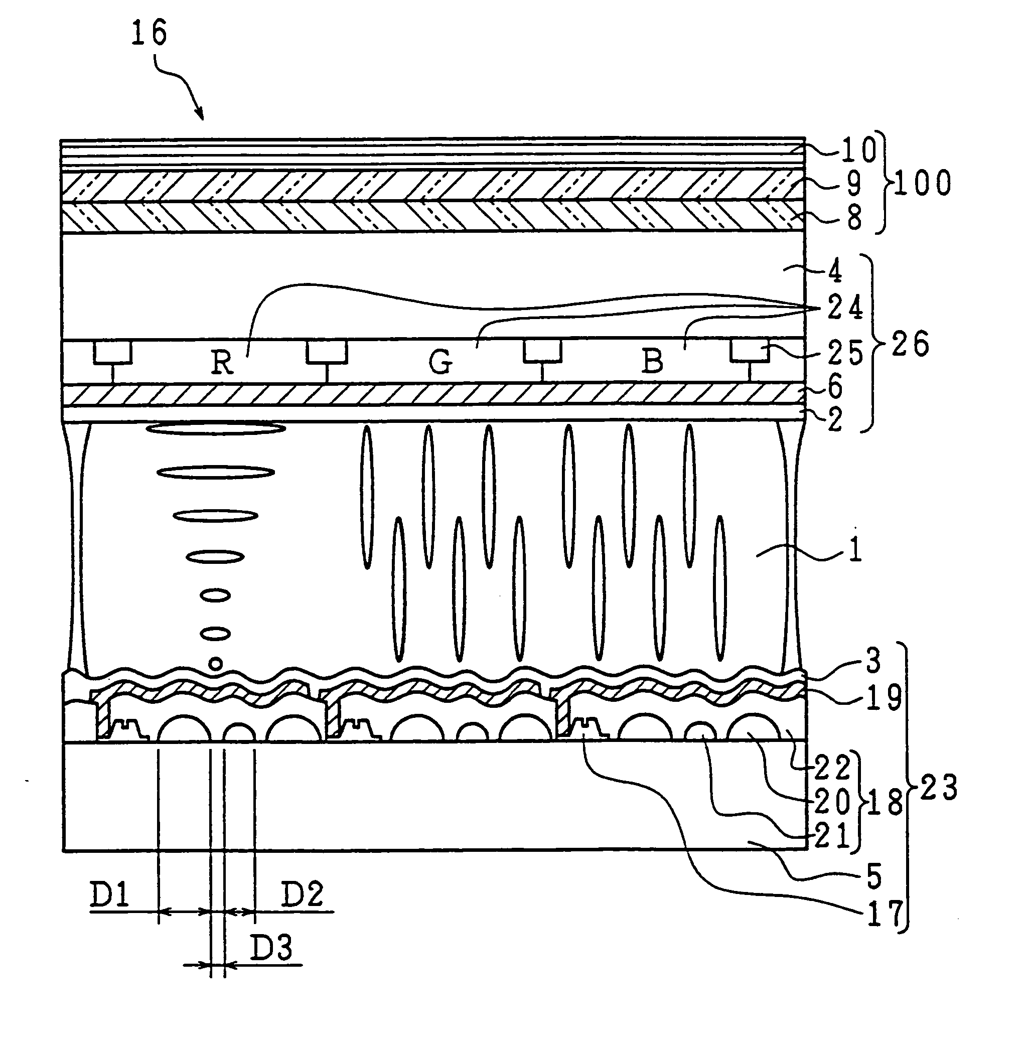
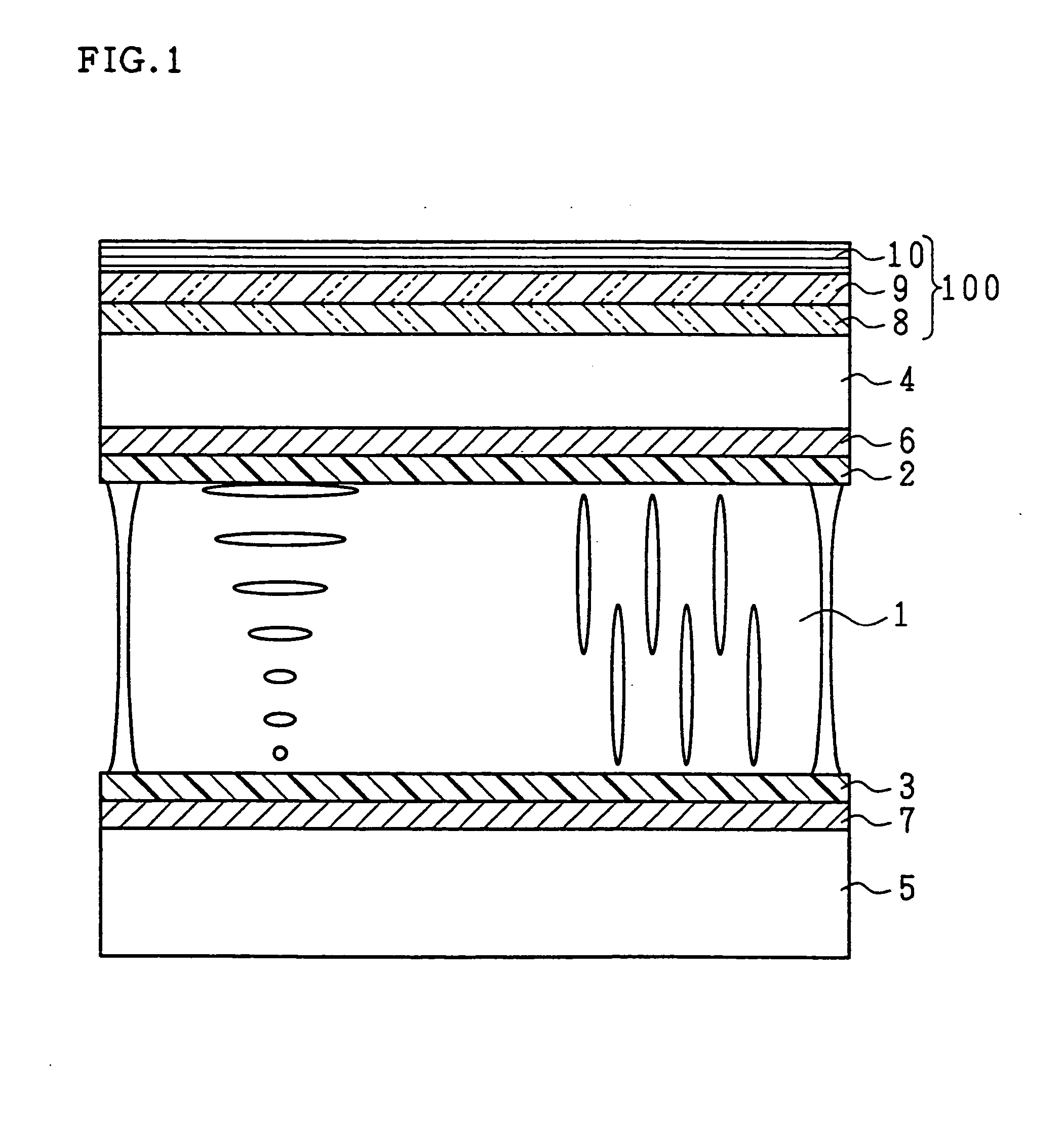
FIG. 1 is a cross-sectional view schematically showing a structure of a major part of a reflective liquid crystal display device of an example in accordance with the present invention. As can be seen from FIG. 1, the reflective liquid crystal display device includes a liquid crystal layer 1 that contains twisted nematic liquid crystal having a positive dielectric anisotropy, sandwiched between a substrate 4 on which an alignment-processed alignment layer 2 is formed and a substrate 5 on which a similarly alignment-processed alignment layer 3 is formed. Further, on the lower substrate 5, there is disposed a light reflective film 7; preferably, the reflecting surface of the light reflective film 7 has such smooth concavities and convexities that preserve the polarization throughout the reflection of light. More preferably, the smooth concavities and co...

example 1

First, as Example 1, the description below will explain an evaluation of specifications of the liquid crystal layer by means of calculation, that are required to specifically design the liquid crystal layer with the optical functions thereof being taken into consideration. For optimum design of the liquid crystal layer, the evaluation function given by Equation (2) is used to evaluate specifications of the liquid crystal layer:

f=1−s32  (2)

Here, s3 is a Stokes parameter to specify a polarization state, more specifically, a Stokes parameter regarding the polarization state of the light that has passed through the liquid crystal layer only once on the reflecting surface. Note that the Stokes parameter used here is normalized.

When the intensity of light is normalized, the polarization state of the perfectly polarized light of which the polarization state can be described by a Stokes parameter having three components: s1 and s2 represent the respective linearly polarized light comp...

example 2

In Example 2, reflective liquid crystal display devices structured as in aforementioned FIG. 1 were fabricated with parameters listed in table 1 to obtain five Samples #2a through #2f.

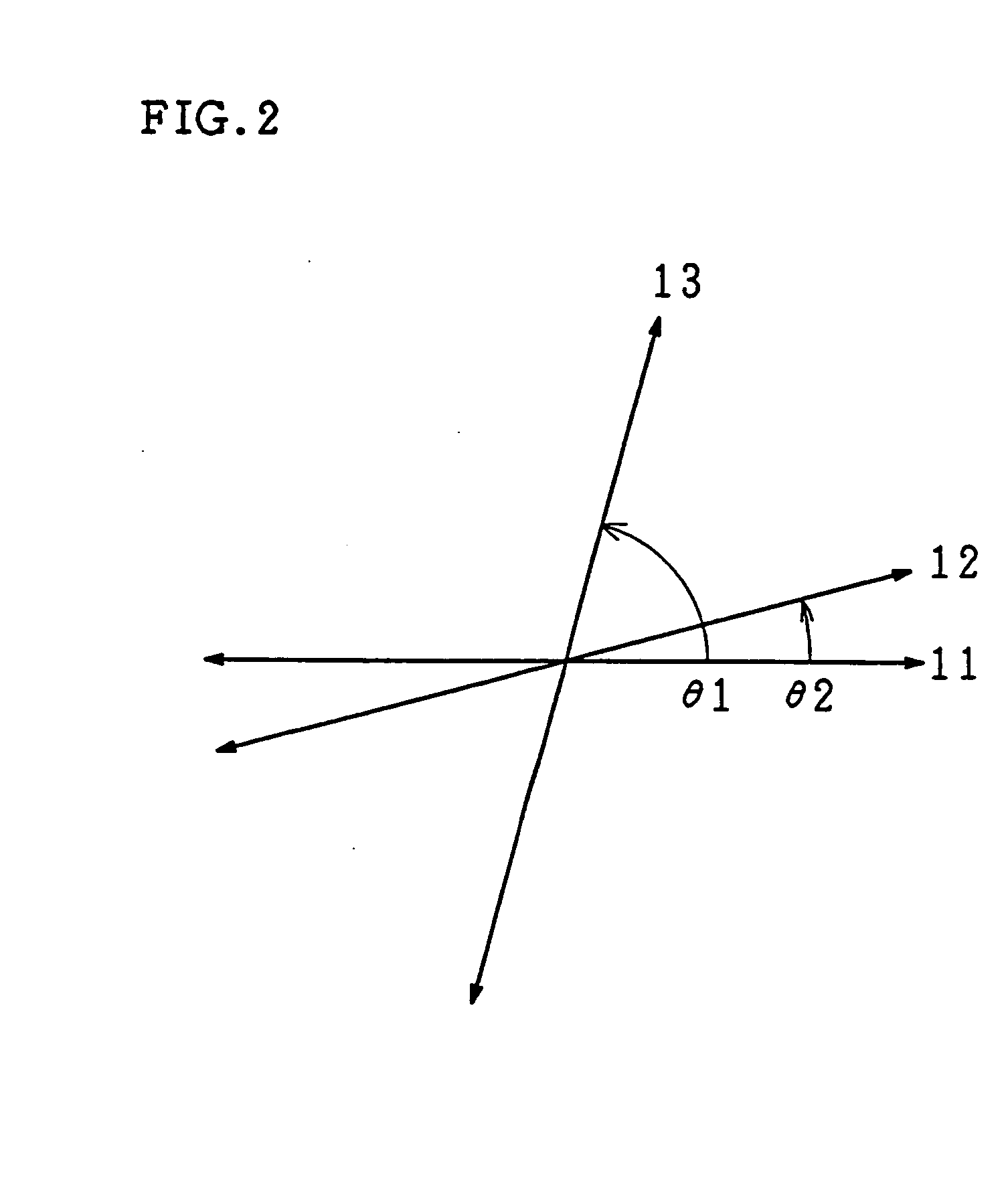
TABLE 1SampleParameter#2a#2b#2c#2d#2e#2fΔnd260330120380260260θ3 (°)404040405520Twist Angle (°)7070707040110θ1 (°)757575757575Retardation Caused by Optical135135135135135135Retardation CompensatorPlate 8θ2 (°)151515151515Retardation Caused by Optical270270270270270270Retardation CompensatorPlate 9

Display results of Samples are shown roughly in Table 2.

TABLE 2SampleVoltage#2a#2b#2c#2d#2e#2f0WhiteYellowishGrayOrangishReddishGrayDisplayWhiteWhiteWhiteDisplayDisplayDisplayVthWhiteWhiteGrayYellowishYellowishGrayDisplayDisplayWhiteWhiteDisplayDisplay1.5 × VthGrayGrayDarkWhiteWhiteDarkGrayDisplayDisplayGray2.0 × VthDarkDark GrayDarkGrayGrayBlackGrayGray3.0 × VthBlackBlackBlackDark GrayDark GrayBlack

Note that Vth refers to threshold voltage values where change in the alignment of the liquid crystal layer...


PUM


Abstract

A reflective color liquid crystal display device with a liquid crystal layer sandwiched between a first substrate having a light reflectibility and a second substrate having a light transmissibility. The liquid crystal layer being composed of twist-aligned nematic liquid crystal having a positive dielectric anisotropy. A circularly polarizing unit, including a single linear polarizer plate, selectively passes either right handed or left handed circularly polarized light out of natural light. The circularly polarizing unit is disposed so that a major surface of the circularly polarizing unit is on a liquid crystal layer side, the circularly polarized light exiting the circularly polarizing unit through the major surface when natural light enters the circularly polarizing unit. Various parameters of the liquid crystal layer are optimized for a liquid crystal layer having a twist angle in the range of 0° to 100°.

Description

TECHNICAL FIELD The present invention relates to reflective liquid crystal display devices for direct view application used in wordprocessors, laptop personal computers, and other office machinery, as well as in a variety of visual and game machines, without a need for a backlight, and also relates to such reflective liquid crystal display devices incorporating a touch panel arranged therefrom. BACKGROUND ART Liquid crystal display devices, being characterized by their thinness and light weight, have successfully found commercial applications as color display devices. Among these color liquid crystal display devices, transmissive liquid crystal display devices provided with a light source for illumination from behind are in particularly widespread use, and are adopted for an increasingly wider variety of applications because of the above-mentioned features. In contrast to the transmission liquid crystal display device, the reflective liquid crystal display device does not require...

Claims


Application Information

Patent Timeline
IPC IPC(8): G02F1/1335G02F1/13363G02F1/139
CPCG02F1/133528G02F1/133553G02F1/133602G02F1/13363G02F1/133634G02F1/1396G02F2413/10G02F2001/1398G02F2202/40G02F2413/03G02F2413/07G02F2413/08G02F2001/133531G02F1/133531G02F1/1398G02F1/1335
Inventor OKAMOTO, MASAYUKIMITSUI, SEIICHISATOH, TAKASHI
Owner SHARP KK
Why Eureka
Try Eureka