Snow-melting LED traffic signal

a technology of led traffic signal and light-emitting diodes, which is applied in the direction of lighting and heating equipment, instruments, and roads, etc., can solve the problems of heavy equipment, inconvenient operation, and inability to meet the needs of traffic, and achieve the effect of satisfying visibility

Inactive Publication Date: 2014-06-05
HARD GIKEN IND +1
View PDF5 Cites 7 Cited by
  • Summary
  • Abstract
  • Description
  • Claims
  • Application Information

AI Technical Summary

Benefits of technology

[0015]The present invention is made to solve the above-mentioned conventional problem, and an object of the present invention is to provide a snow-melting LED traffic signal which can inhibit snow accretion, ice accretion, frost accretion, freeze of snow, freeze of ice, freeze of frost, and the like promptly without fail and can obtain satisfactory visibility.

Problems solved by technology

In Japan, which being long in a north-south direction, except for southern parts thereof and the like, snow, ice, or frost accretes to traffic signals in winter or the like to lower the visibility of the traffic signals, which is an obstacle to safe road traffic.
However, an LED traffic signal is more excellent in energy efficiency with lower power consumption, but generates less heat compared to those of a conventional traffic signal, which adversely affect the situation to thereby arise a problem frequently such that snow or ice accretes to traffic signals in winter or the like and a signal light is hardly visible, whereby leading to a serious accident.
When snow accumulates, a problem arises that a snow buildup on or an icicle hanging down from the eave weights the signal no matter whether the signal is of a vertical type or of a horizontal type, which places a heavy load on a signal pole to be a cause of a failure.
Therefore, both for the purpose of ensuring the visibility of traffic signals and for the purpose of maintaining bodies of the signals, man power has been used to remove snow, icicles, and the like attached to traffic signals installed in snowy areas and high-altitude areas, but this work requires enormous efforts under severe circumstances.
However, such a device is heavy and large to some extent.
This LED traffic signal exhibited the effect of inhibiting snow accretion, ice accretion, frost accretion, freeze of snow, freeze of ice, freeze of frost, and the like to some extent, but the snow melting speed was not so high and far infrared radiation was not emitted substantially uniformly over substantially the entire surface of the LED signal light.
Thus, the LED traffic signal was not necessarily satisfactory.

Method used


Image

  • Snow-melting LED traffic signal
  • Snow-melting LED traffic signal
  • Snow-melting LED traffic signal

Examples


Embodiment Construction

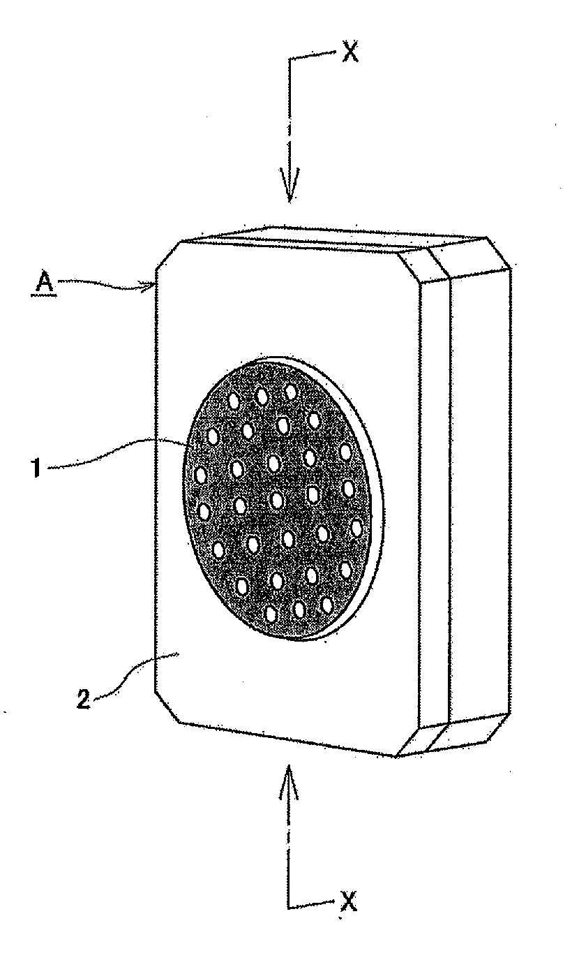
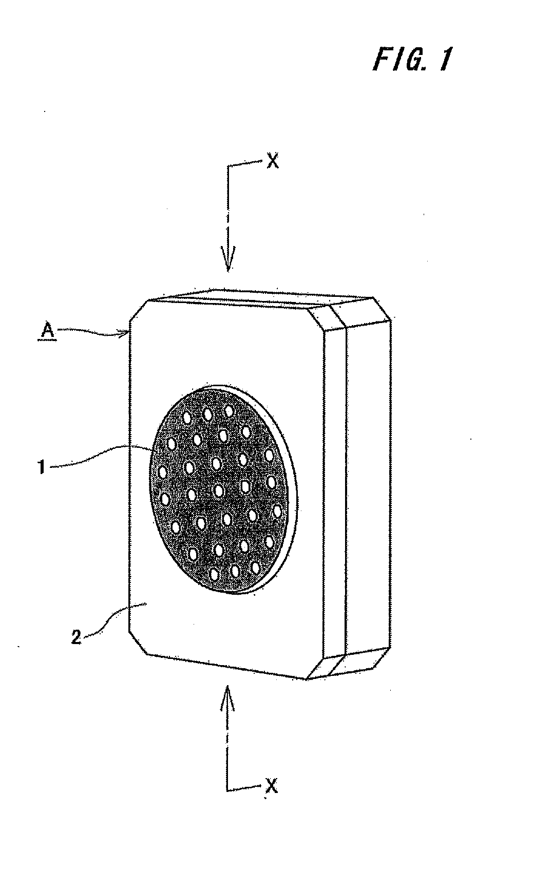
[0039]The present invention relates to a snow-melting LED traffic signal including:

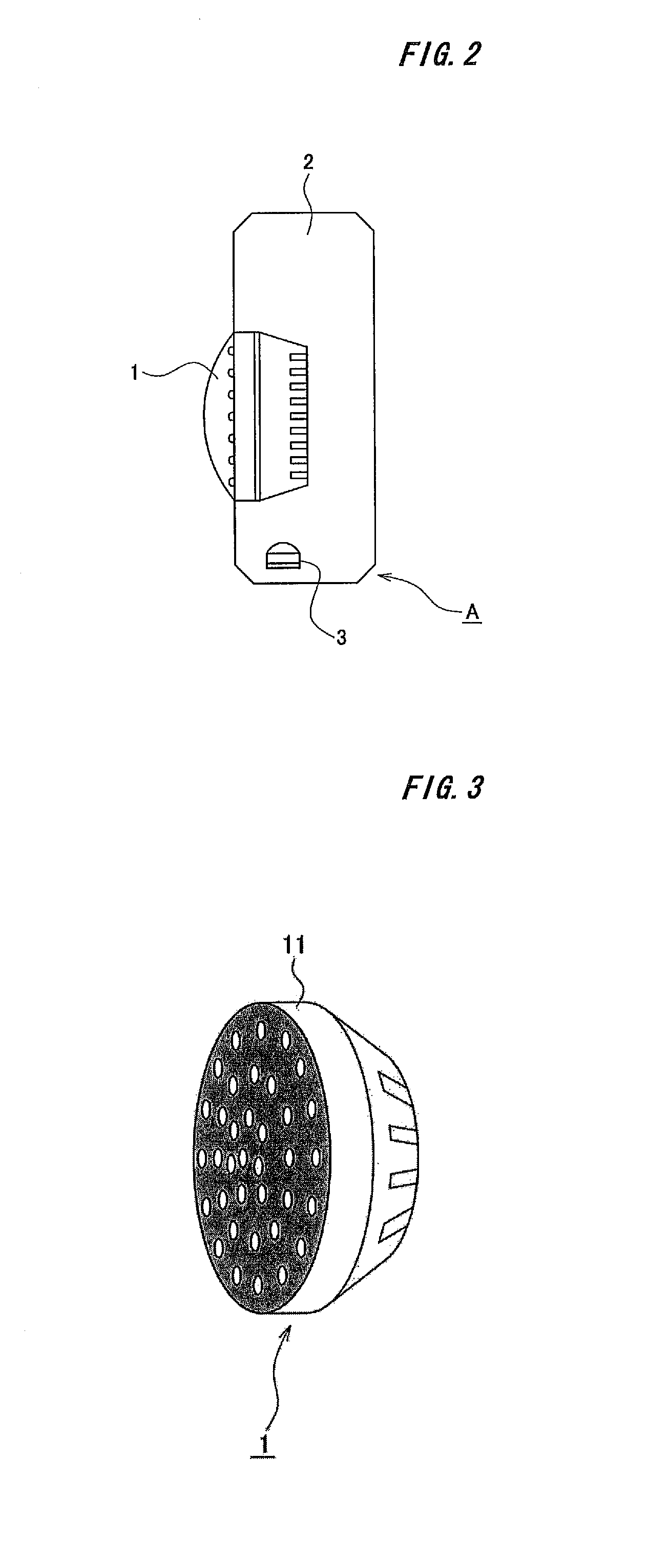
[0040]an LED signal light 1 including in order:[0041]a lens cover 11;[0042]a heat generating sheet 12;[0043]an LED mask plate 13;[0044]an LED lens module 14; and[0045]a printed board protection cover 15; and

[0046]a signal body 2 for housing the LED signal light 1.

[0047]The present invention is described in detail in the following with reference to the attached drawings.

[0048]FIG. 1 is a perspective view illustrating a snow-melting LED traffic signal according to an embodiment of the present invention. FIG. 2 is a sectional explanatory view taken along the line X-X of FIG. 1. FIG. 3 illustrates an LED signal light 1 according to the embodiment. FIG. 4 is an exploded explanatory view of the LED signal light 1 illustrated in FIG. 3. FIG. 5 is an exploded explanatory view of a heat generating sheet 12.

[0049]In the figures, a reference character A denotes a snow-melting LED traffic signal according to the ...


PUM


Abstract

Provided is an LED traffic signal which can inhibit snow accretion, ice accretion, frost accretion, freeze of snow, freeze of ice, freeze of frost, and the like promptly without fail and which can obtain satisfactory visibility. The snow-melting LED signal includes: an LED signal light including in order: a lens cover; a heat generating sheet; an LED mask plate; an LED lens module; and a printed board protection cover; and a signal body for housing the LED signal light.

Description

BACKGROUND OF THE INVENTION[0001]1. Field of the Invention[0002]The present invention relates to a snow-melting light-emitting diode (LED) traffic signal, which can inhibit snow accretion, ice accretion, frost accretion, freeze of snow, freeze of ice, freeze of frost, and the like promptly without fail, and can obtain satisfactory visibility.[0003]2. Description of the Related Art[0004]A traffic signal is a device which is indispensable for ensuring safety of road traffic and smoothness of a traffic flow.[0005]In recent years, installation of, as such traffic signals, LED traffic signals has already been carried out in the respective prefectures here in Japan as a national policy making use of characteristics of LEDs such as low power consumption and long life. At present, ⅓ to ¼ of incandescent signals installed in Japan have been replaced by LED signals.[0006]In Japan, which being long in a north-south direction, except for southern parts thereof and the like, snow, ice, or frost ...

Claims


Application Information

Patent Timeline
Patent Type & Authority Applications(United States)
IPC IPC(8): F21V29/00
CPCF21V29/008B61L5/1827B61L2207/02F21V5/045F21W2111/02F21V29/83F21V29/90F21Y2105/10F21Y2115/10Y02E60/10H05B1/02H01M10/6561
Inventor SUZUKI, TOSHIHIROIMAO, MICHIAKI
Owner HARD GIKEN IND
Why Eureka
Try Eureka