Transflective liquid crystal display device and color liquid crystal display device

a liquid crystal display device and liquid crystal display technology, applied in non-linear optics, instruments, optics, etc., can solve the problems of inability to view the display, inability to ensure sufficient contrast in an environment with intense ambient light, and inability to power-up the light source, etc., to achieve the effect of low power consumption

Active Publication Date: 2005-12-08
SANYO ELECTRIC CO LTD
View PDF21 Cites 87 Cited by
  • Summary
  • Abstract
  • Description
  • Claims
  • Application Information

AI Technical Summary

Benefits of technology

[0036] By employing such a relationship and a structure, it is possible to realize a display of low power consumption and without coloring for any of thr

Problems solved by technology

However, because the light source is always being switched on to achieve display, power consumption by the light source is unavoidable, and, moreover, there is a disadvantage that sufficient contrast cannot be secured in an environment with intense ambient light such as outdoors during daytime.
The reflective LCD has a characteristic that a sufficient contrast can be obtained when the environment is bright suc

Method used


Image

  • Transflective liquid crystal display device and color liquid crystal display device
  • Transflective liquid crystal display device and color liquid crystal display device
  • Transflective liquid crystal display device and color liquid crystal display device

Examples


first preferred embodiment

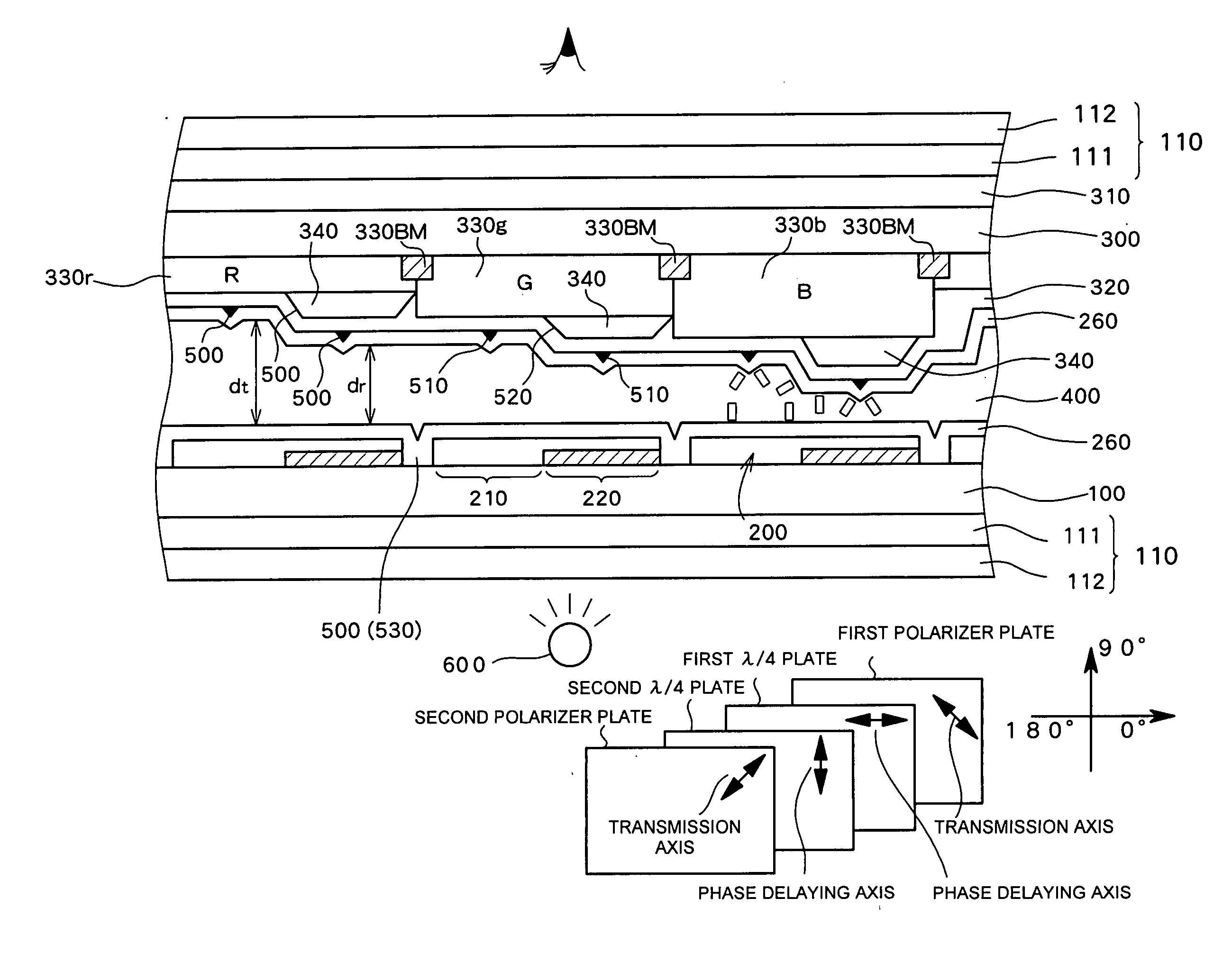
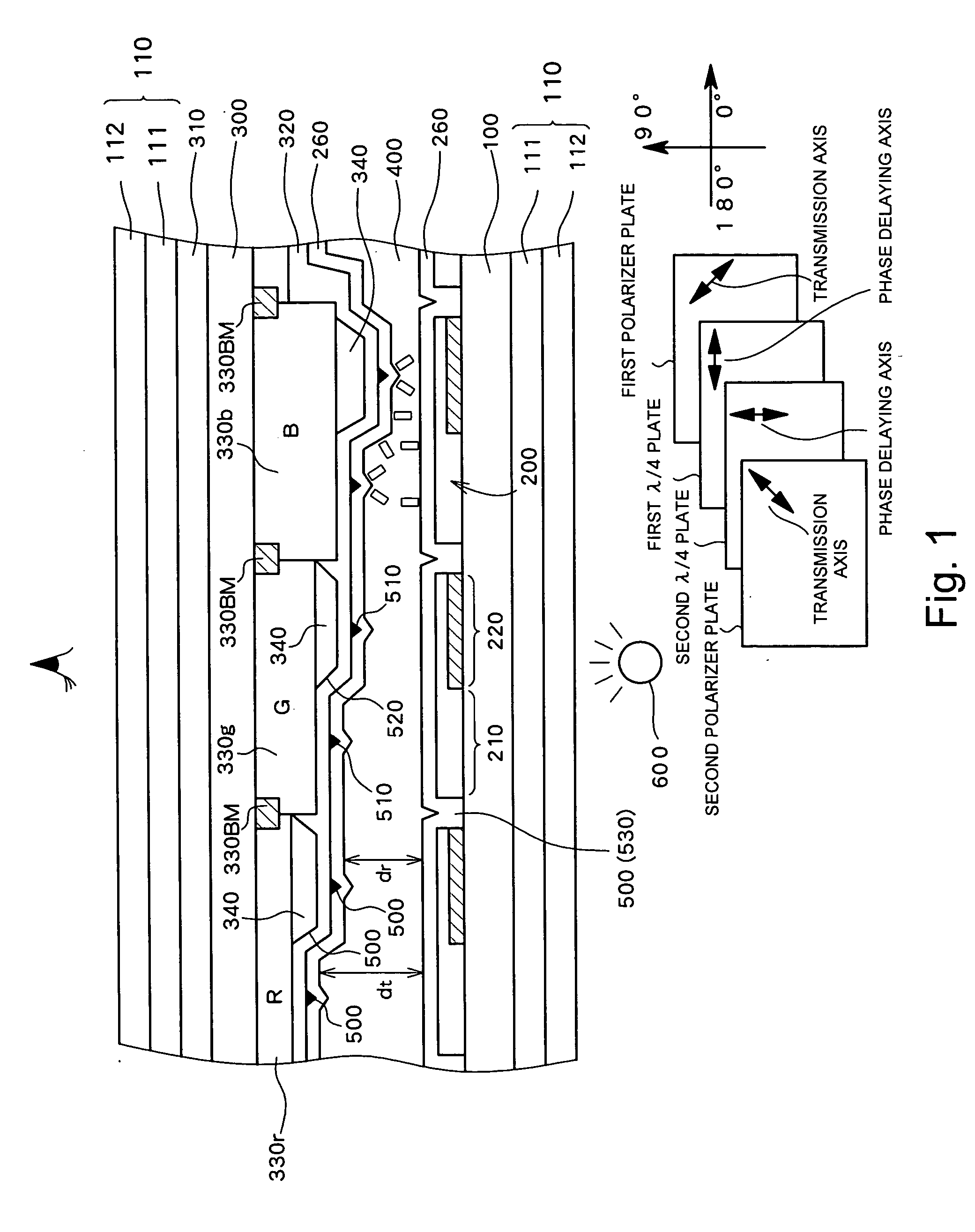
[0058]FIG. 1 schematically shows a cross sectional structure of a transflective active matrix LCD which is used as the transflective LCD according to a first preferred embodiment of the present invention. The transflective LCD according to the first preferred embodiment comprises a plurality of pixels, wherein a first substrate and a second substrate on which a first electrode 200 and a second electrode 320 are formed respectively on a side opposing each other are adhered to each other with a liquid crystal layer 400 therebetween, and a transmissive region 210 and a reflective region 220 are formed in each pixel region.

[0059] A vertical alignment liquid crystal having a negative dielectric constant anisotropy is used as the liquid crystal layer 400 and an alignment controller 500 (alignment divider) for dividing a pixel region into a plurality of alignment regions is provided on the side of the second substrate or on the side of the first substrate. As shown in FIG. 1, the alignmen...

second preferred embodiment

[0121] A second preferred embodiment of the present invention will now be described which is a configuration for improving a display quality in color display. In the below description, color display on a vertical alignment liquid crystal display device is exemplified.

[0122] A vertical alignment liquid crystal display device has a wide viewing angle characteristic and a high contrast characteristic, and has an advantage that no rubbing process of the alignment film is necessary.

[0123] In the vertical alignment liquid crystal display device, because the liquid crystal has a negative dielectric constant anisotropy, the liquid crystal molecules forming the liquid crystal has a characteristic that the liquid crystal tends to be directed in a direction perpendicular to the direction of the electric field. In such a liquid crystal display device, a vertical alignment film is employed as the alignment film for controlling the initial alignment of the liquid crystal and an organic material...

third preferred embodiment

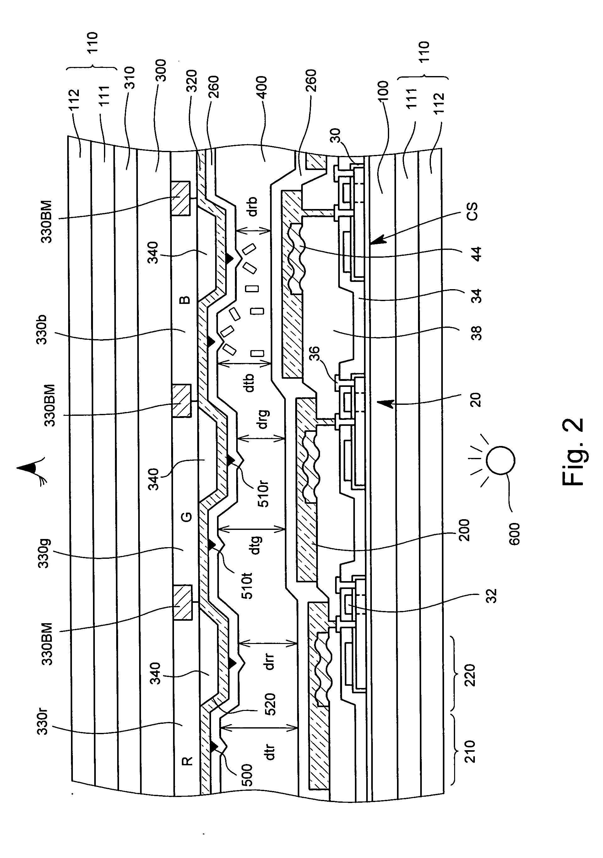
[0143] A third preferred embodiment of the present invention will now be described referring to the drawings. FIG. 18 is a diagram schematically showing a cross sectional structure of a vertical alignment liquid crystal display device according to the third preferred embodiment of the present invention. The components identical to those in the second preferred embodiment are assigned the same reference numerals and will not described again.

[0144] In the third preferred embodiment, in order to achieve different optimum thicknesses of gap G in the red, green, and blue pixels, in addition to the red, green, and blue color filter layers 330r, 330g, and 330b formed on the side of the second glass substrate 300 and the projections 340 (340r, 340g, and 340b) for adjusting the gap difference between the transmissive region and the reflective region, an adjusting layer (gap layer) 350 for adjusting the gap difference for red, green, and blue is provided. More specifically, in the blue and g...


PUM


Abstract

A vertical alignment liquid crystal layer is sealed between a first substrate having a first electrode and a second substrate having a second electrode, each pixel region has a reflective region and a transmissive region, and a gap adjusting section is provided on one of sides of the first substrate and the second substrate which sets a thickness (gap) d of the liquid crystal layer which controls a phase difference of incident light to the liquid crystal layer so that a gap dr in the reflective region is smaller than a gap dt in the transmissive region. An alignment controller which divides alignment of the liquid crystal within a pixel region is provided in the pixel region on at least one of the sides of the first substrate and the second substrate. It is also possible to optimize by changing the gap in red, green, and blue.

Description

CROSS-REFERENCE TO RELATED APPLICATIONS [0001] The entire disclosure of Japanese Patent Application Nos. 2004-152609, 2004-214628, 2004-214629 and 2004-347905 including specification, claims, drawings and abstract is incorporated herein by reference.BACKGROUND OF THE INVENTION [0002] 1. Field of the Invention [0003] The present invention relates to a transflective (semitransmissive) liquid crystal display device in which both a reflective region and a transmissive region are provided in each pixel. [0004] 2. Description of the Related Art [0005] Because liquid crystal display (hereinafter simply referred to as “LCD”) devices have advantages such as thin thickness and low power consumption, the LCD devices are currently widely in use as a computer monitor and a monitor for a portable information device. In an LCD, liquid crystal is sealed between a pair of substrates and alignment of the liquid crystal positioned between the substrates is controlled by electrodes formed on the substr...

Claims


Application Information

Patent Timeline
IPC IPC(8): G02F1/1333G02F1/1335G02F1/1337G02F1/139
CPCG02F1/133371G02F1/133514G02F1/1337G02F1/133753G02F1/1393G02F1/133555G02F1/1335
Inventor KOMA, NORIOMITSUI, MASASHIINOUE, KAZUHIROMAEDA, KAZUYUKIYAMADA, TSUTOMUAOTA, MASAAKIKAMETANI, MASAYUKI
Owner SANYO ELECTRIC CO LTD
Why Eureka
Try Eureka