Unlock instant, AI-driven research and patent intelligence for your innovation.

Erase verify for non-volatile memory

a non-volatile memory and verification technology, applied in the field of memory devices, can solve the problems of false reading, small current leakage, and erasing a memory cell

Inactive Publication Date: 2005-12-08
MICRON TECH INC
View PDF18 Cites 0 Cited by
  • Summary
  • Abstract
  • Description
  • Claims
  • Application Information

AI Technical Summary

Benefits of technology

The present invention addresses issues with memory devices by providing a non-volatile memory with a verify circuit to determine if memory cells have a program level within a window defined by reference signals. The verify circuit can selectively couple to bit lines and compare the current or voltage with a reference current or voltage to determine if the memory cell is programmed correctly. This ensures the accuracy and reliability of the memory device. Additionally, the invention provides a method for erase verifying a non-volatile memory cell by generating reference currents or voltages and comparing the bit line current or voltage with the reference currents or voltages. This allows for more efficient and effective erasure of the memory cells.

Problems solved by technology

A problem that may be encountered in erasing a memory cell is over-erasure.
This occurs when too many electrons are removed from the floating gate during an erase operation.
An over-erased cell has a slight positive charge that biases the memory cell thereby causing a small current leak.
This current leak can cause a false reading.
Another problem that may be encountered is under-erased memory cells.
The completion of both steps takes a significant amount of time.

Method used


Image

  • Erase verify for non-volatile memory
  • Erase verify for non-volatile memory
  • Erase verify for non-volatile memory

Examples


Embodiment Construction

[0027] In the following detailed description of the preferred embodiments, reference is made to the accompanying drawings that form a part hereof, and in which is shown by way of illustration specific preferred embodiments in which the inventions may be practiced. These embodiments are described in sufficient detail to enable those skilled in the art to practice the invention, and it is to be understood that other embodiments may be utilized and that logical, mechanical and electrical changes may be made without departing from the spirit and scope of the present invention. The following detailed description is, therefore, not to be taken in a limiting sense, and the scope of the present invention is defined only by the claims.

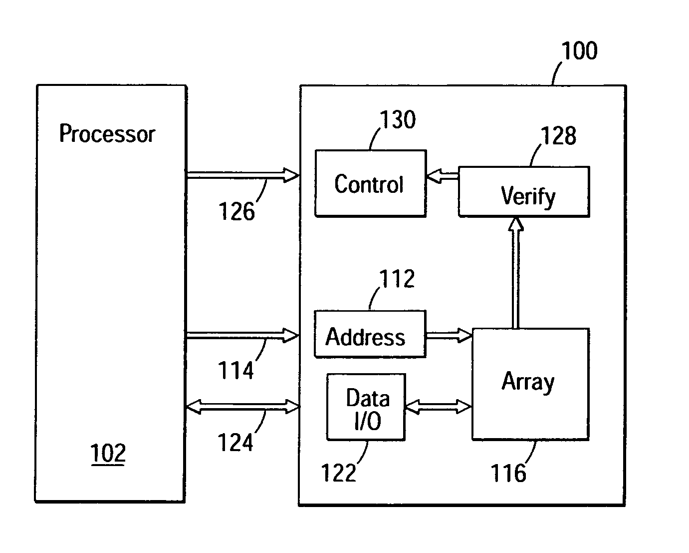
[0028]FIG. 1 illustrates a block diagram of a flash memory device 100 that is coupled to an external processor 102. The memory device 100 has been simplified to

[0029] focus on features of the memory that are helpful in understanding the present invention. The...


PUM


Abstract

A memory device verify system determines a state of memory cells in a memory. The memory includes a memory array having a plurality of memory cells coupled to bit lines. A verify circuit is coupled to the bit lines to determine if memory cells have a erase level that is within predetermined upper and lower limits. The verify circuit can include first and second comparators. In one embodiment, the first comparator is used to compare a bit line current with an upper first reference current. The second comparator is used to compare a bit line current with a lower second reference current. The comparator circuit is not limited to reference currents, but can use reference voltages to compare to a bit line voltage. The verify circuit, therefore, eliminates the need for separate bit line leakage testing to identify over-erased memory cells.

Description

CROSS-REFERENCE TO RELATED APPLICATION [0001] This application is a Divisional of U.S. patent application Ser. No. 09 / 943,479, filed Aug. 30, 2001 and titled, “ERASE VERIFY FOR NON-VOLATILE MEMORY,” which is commonly assigned and incorporated by reference in its entirety herein.TECHNICAL FIELD OF THE INVENTION [0002] The present invention relates generally to memory devices and in particular the present invention relates to determining erase levels of memory cells in non-volatile memory devices. BACKGROUND OF THE INVENTION [0003] The use of non-volatile memory systems that maintain data integrity when a power supply is removed are expanding rapidly in integrated circuit technology. A class of non-volatile memory systems having memory cells which has a source, a drain, a channel, a floating gate over the channel and a control gate are widely used. Two popular types of non-volatile memory designs in this class is the electronically erasable and programmable read only memories (EEPROM)...

Claims


Application Information

Patent Timeline
Patent Type & Authority Applications(United States)
IPC IPC(8): G11C16/34
CPCG11C16/3404G11C16/344
Inventor CHEVALLIER, CHRISTOPHE J.
Owner MICRON TECH INC