Subcutaneous analyte sensor

an analyte sensor and subcutaneous technology, applied in the field of implantable sensors, can solve the problems of large and expensive apparatus, no of these methods has yet acquired practical significance, and signal instability

Inactive Publication Date: 2005-12-08
ROCHE DIABETES CARE INC
View PDF17 Cites 162 Cited by
  • Summary
  • Abstract
  • Description
  • Claims
  • Application Information

AI Technical Summary

Problems solved by technology

As such, they are prone to inherent signal instability of the sensor, and they require that chemicals (e.g., enzymes and mediators) be introduced into the patient's body.
However, none of these methods has as yet acquired practical significance.
Some of them require large and expensive apparatus, generally unsuitable for routine analysis and home monitoring of a patient.
This spectral region is not suitable for invasive analytical determination of glucose because of the strong absorption of water, which is present in high concentration in biological matrices.
Developing a practical implantable glucose sensor on the basis of these principles presents certain problems.
These problems result particularly from the fact that the effective signal (the change in the absorption spectrum due to a change in glucose concentration) is generally very small.
Sensitivity is always an issue in absorption measurements because of the difficulty in observing a small effective signal superimposed on a relatively much larger background signal.
However, in this case the difficulty is enhanced due to background signals resulting from the spectral absorption of water.
Some attempts have been made to solve this problem (see e.g., EP-A-0 160 768; U.S. Pat. No. 5,028,787; and WO 93 / 00856); however, these attempts have not been successful in providing a practical and functional implantable glucose sensor based on absorption principles.

Method used


Image

  • Subcutaneous analyte sensor
  • Subcutaneous analyte sensor
  • Subcutaneous analyte sensor

Examples


first embodiment

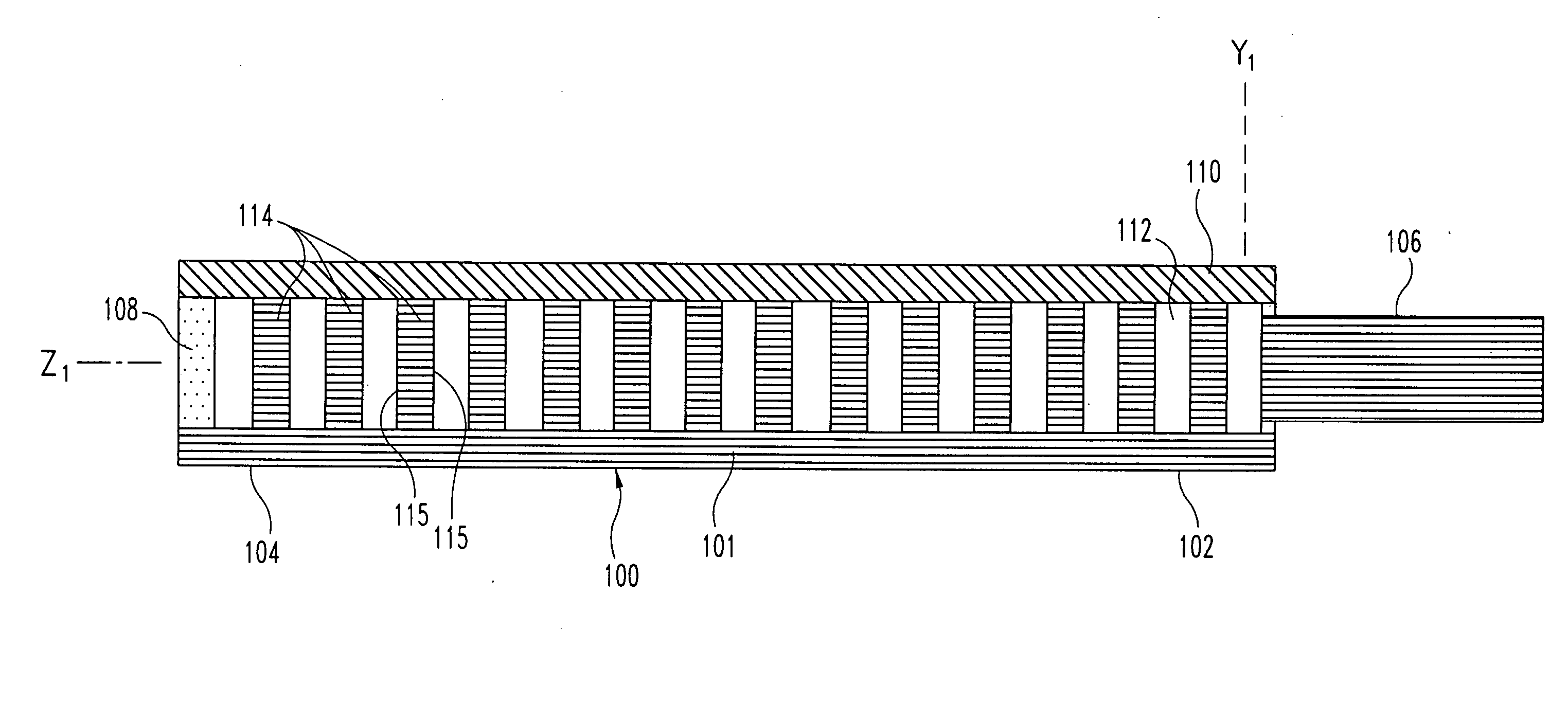
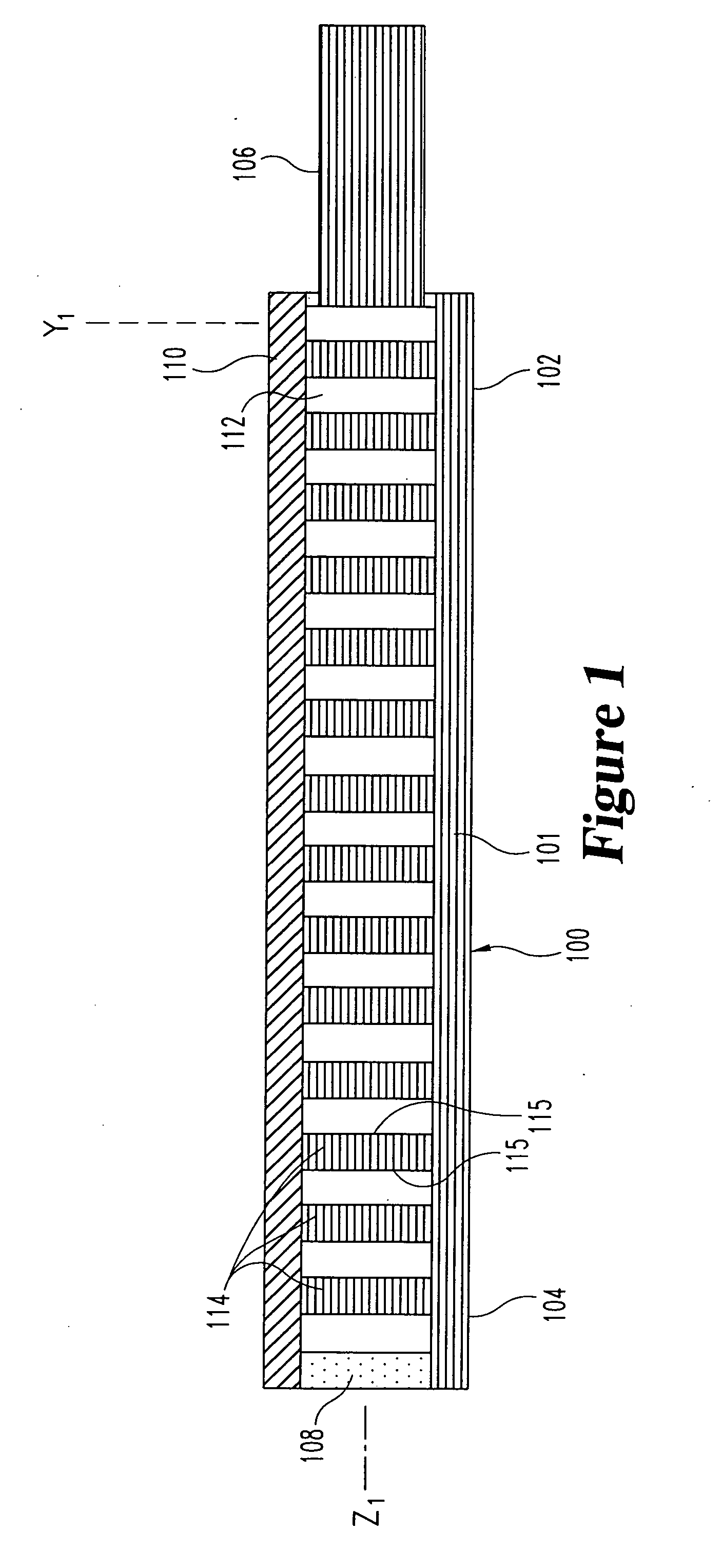
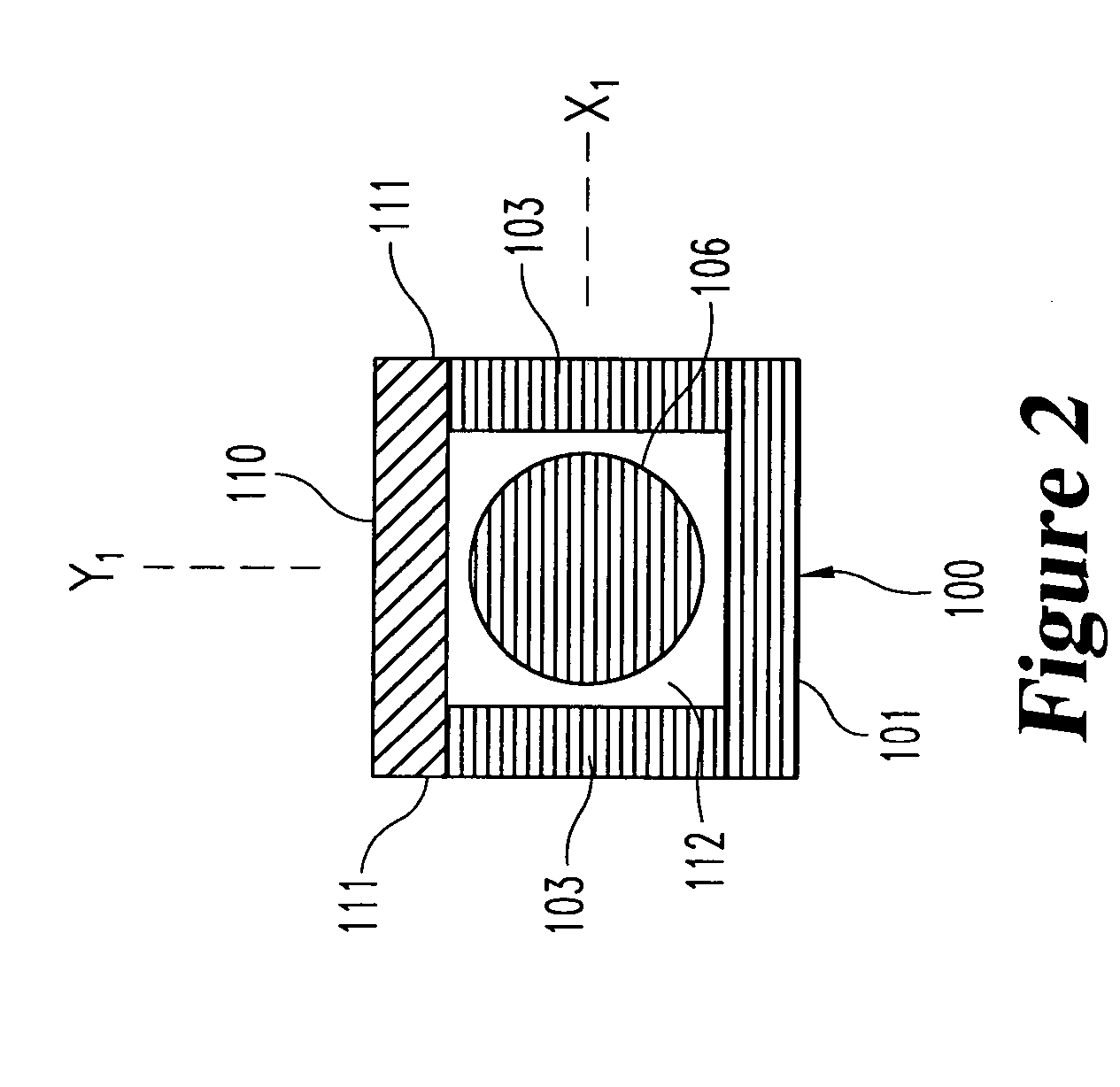
[0061] the optical-sensing element of the invention is illustrated in FIGS. 1-3. The optical-sensing element includes a body 100, a semi-permeable membrane 110 and a refractive element 114. The body 100 and membrane 110 are oriented to define a cavity 112. The refractive element 114 and the analyte or analytes of interest (not shown) are disposed in the cavity 112. The semi-permeable membrane 110 is substantially permeable to the analyte(s), but substantially impermeable to background species in the biological matrix.

[0062] Preferably, the body 100 of the optical-sensing element has a generally “U” or “V”-shaped cross-section, and comprises a molded plastic. The body 100 has a base portion 101 and two opposing side walls 103. Each of the side walls 103 includes an upper edge 111. The body 100 has a proximal end 102 and a distal end 104, and is preferably less than 2 mm in length. A light-transmitting conduit 106, here a single optical fiber, is optically coupled to the proximal end ...

second embodiment

[0067] the invention is illustrated in FIGS. 4-6. The body 200 of the optical-sensing element comprises two parallel, elongated members 203, each having an upper edge 211 and a lower edge 213. The body is preferably formed of molded plastic and is dimensioned in similar manner to the embodiment of FIGS. 1-3. The body 200 also includes a proximal end 202 and a distal end 204. A light-transmitting conduit 206, here a single optical fiber, is sealed in an orifice in the proximal end 202. The distal end 204 preferably comprises a light-absorbing material 208. In this embodiment, a first semi-permeable membrane 210 is attached to the top edges 211 of the elongated members 203, and a second semi-permeable membrane 209 is attached to the bottom edges 213 of the elongated members 203.

[0068] The elongated members 203 and semi-permeable membranes 209 and 210 define a cavity 212. The cavity contains the analyte of interest (not shown) and a refractive element 214. The refractive element compri...

third embodiment

[0069] the invention is illustrated in FIGS. 7-9. In this embodiment, the body 300, base portion 301, side walls 303, light-transmitting conduit 306, light-absorbing material 308, membrane 310, edges 311, cavity 312, and respective proximal and distal ends 302 and 304 are as described in the embodiment of FIGS. 1-3. The refractive element 314 comprises a plurality of beads, which provide a plurality of reflective or refractive surfaces 315. The composition of the beads is normally not important, as long as they provide suitable reflective or refractive surfaces. Glass beads, or beads formed from polymers such as polystyrene, are particularly suitable. The composition, diameter, and number of the beads can be varied to achieve a packing arrangement which provides optimal amplification of light by multiple reflections off the bead surfaces 315. A similar effect is achieved when refractive powders are provided in the, cavity in place of the beads.


PUM

PropertyMeasurementUnit
refractive indexaaaaaaaaaa
wavelengthsaaaaaaaaaa

Abstract

Assembly and method for measuring the concentration of an analyte in a biological matrix. The assembly includes an implantable optical-sensing element that comprises a body, and a membrane mounted on the body in a manner such that the membrane and the body define a cavity. The membrane is permeable to the analyte, but is impermeable to background species in the biological matrix. A refractive, element is positioned in the cavity. A light source transmits light of a first intensity onto the refractive element, and a light detector receives light of a second intensity that is reflected from the cavity. A controller device optically coupled to the detector compares the first and second light intensities, and relates the intensities to analyte concentration.

Description

BACKGROUND OF THE INVENTION [0001] The present invention relates to implantable sensors, and more specifically, to implantable sensors for monitoring levels of analytes, such as glucose. [0002] Several designs for implantable sensors that allow continuous in vivo monitoring of levels of analytes such as glucose have been previously described. Many such designs are based on electrochemical analyte detection principles. As such, they are prone to inherent signal instability of the sensor, and they require that chemicals (e.g., enzymes and mediators) be introduced into the patient's body. [0003] A second approach involves physical (i.e. reagent-free) methodology. A review of physical methods for determinations of glucose in vivo is given in J. D. Kruse-Jarres “Physicochemical Determinations of glucose in vivo,” J. Clin. Chem. Clin. Biochem. 26 (1988), pp. 201-208. Nuclear magnetic resonance (No), electron spin resonance (ESR), and infrared (IR) spectroscopy are named, among others, as ...

Claims


Application Information

Patent Timeline
Patent Type & Authority Applications(United States)
IPC IPC(8): A61B5/00G01N21/01A61B5/145A61B5/1459G01N21/41
CPCA61B5/14532A61B5/1459
Inventor GERBER, MARTINESSENPREIS, MATTHIASPETRICH, WOLFGANG
Owner ROCHE DIABETES CARE INC
Why Eureka
Try Eureka