Coaxial connector

Inactive Publication Date: 2005-12-08
MOLEX INC
View PDF12 Cites 6 Cited by
  • Summary
  • Abstract
  • Description
  • Claims
  • Application Information

AI Technical Summary

Benefits of technology

[0012] The conductive layer of the coaxial cable is penetrated directly through the rear end of the connection member and is adjacent to the inscribed surface for soldering, so that the connection between the coaxial connector and the coaxial cable is easy, and the position of the coaxial cable is accurate. Moreover, because it is not necessary to spread the conductive layer of the coaxial cable, it maint

Problems solved by technology

Second, the conductive layer 52 is spread, so the stability thereof is impacted and it causes loss of signals thereof.
Third, it is time-consuming and hard to position to spread the conductive layer 52 and to dispose the conductive term

Method used


Image

  • Coaxial connector
  • Coaxial connector
  • Coaxial connector

Examples


first embodiment

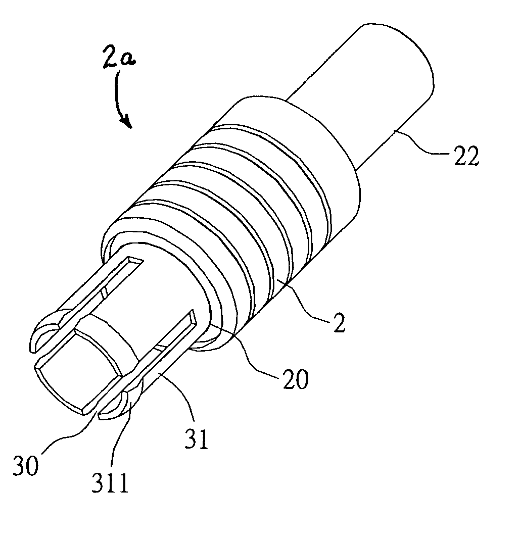
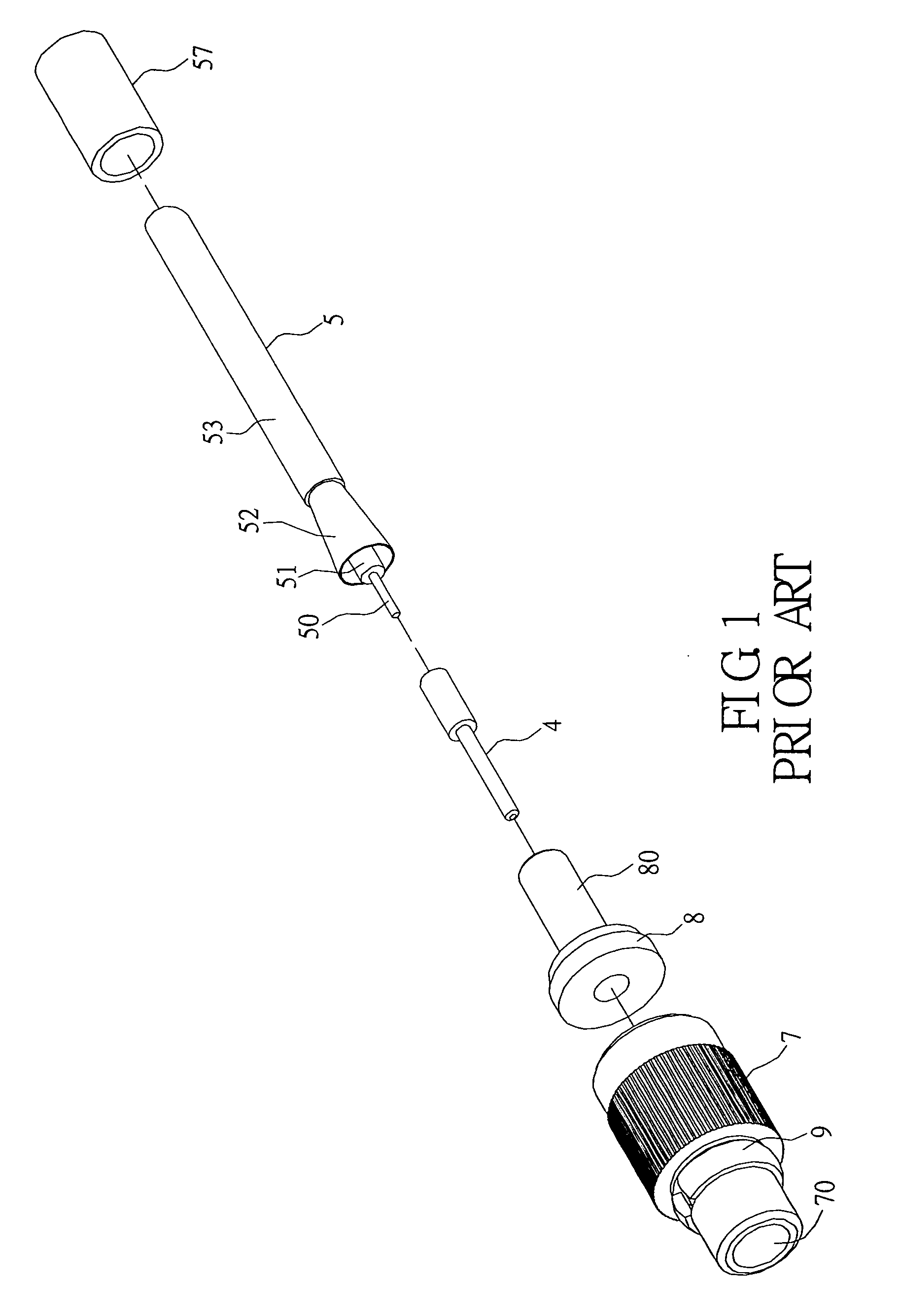
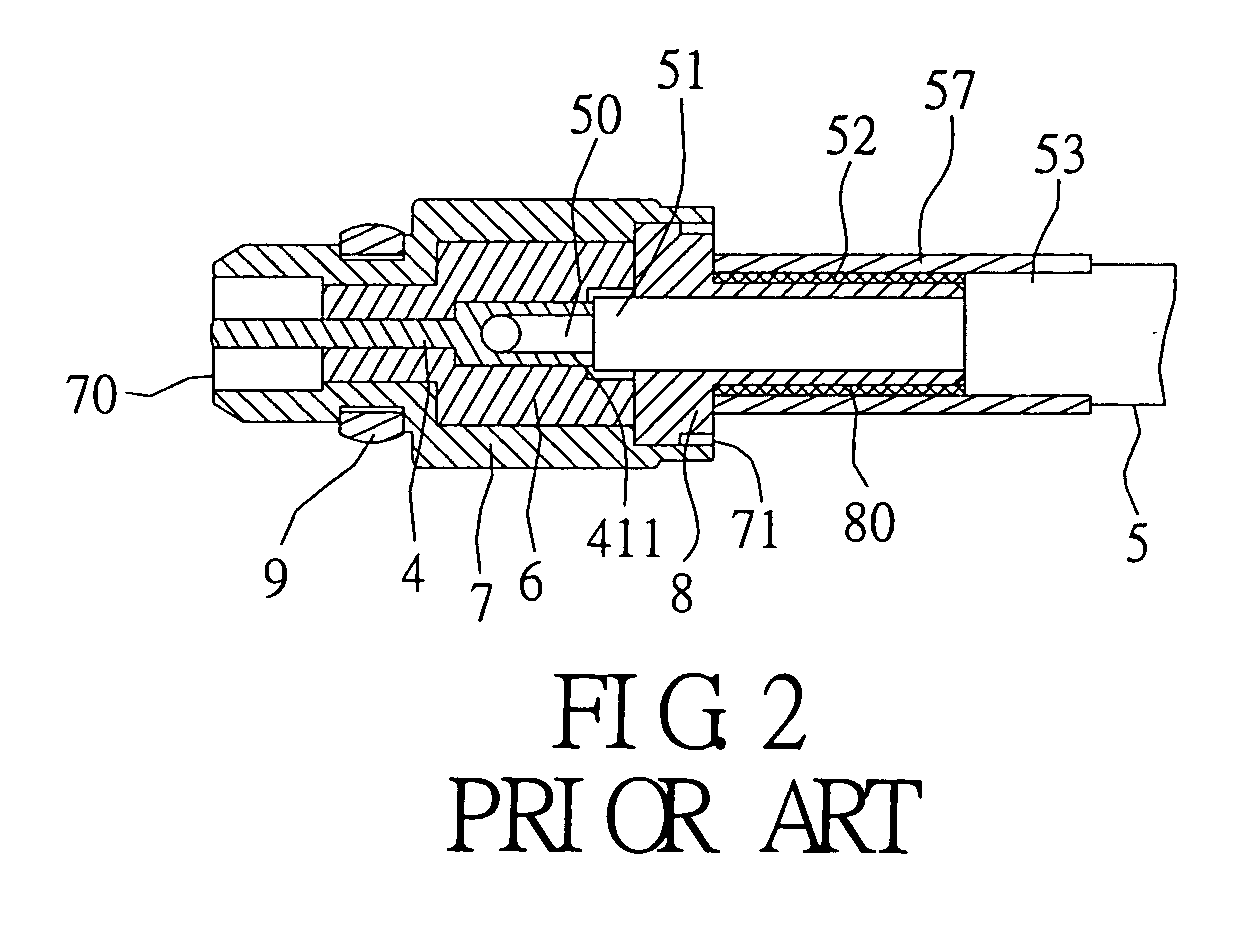
[0026]FIGS. 5-7 show the present invention. The present invention provides a coaxial connector for connection with a coaxial cable 5. The coaxial cable 5 has a core 50, an inner insulative layer 51, a conductive layer 52, and an outer insluative layer 53 arranged from an inside thereof to an outside thereof in order. The conductive layer 52 can be a metal braid. The coaxial connector comprises an insulative sleeve 1, a connection member 2a, and a conductive terminal 4.

[0027] The insulative sleeve 1 is substantially a cylinder. The insulative sleeve 1 has an aperture 10. The insulative sleeve 1 has an annular groove 11 formed on an outer circumferential surface thereof. The insulative sleeve 1 has a concavity 12 formed at a rear end thereof.

[0028] The connection member is a tubular conductive structure. The connection member has an inscribed surface 221 formed at a rear end thereof. In this embodiment, the connection member includes a body element 2 and a resilient element 3. The bo...

second embodiment

[0033]FIGS. 8-10 show the present invention. The second embodiment is a mating connector of the coaxial connector of the first embodiment. The coaxial connector of the second embodiment comprises an insulative sleeve 1, a connection member 2a′, and a conductive terminal 4′. The insulative sleeve 1 is the same as that of the first embodiment. The conductive terminal 4′ is a female terminal, and the contact portion 40′ thereof is different from the contact portion 40 of the first embodiment. The connection member is a tubular conductive structure. The connection member has an inscribed surface 32′ formed at a rear end thereof. In this embodiment, the connection member includes a body element 2′ and an extension element 3′. The body element 2′ has a front opening 20′ and a rear opening 21′ respectively formed at a front end thereof and a rear end thereof. The body element 2′ has a guiding slant 201′ disposed at the front opening 20′ for guiding the guiding angles 312 of the resilient a...


PUM


Abstract

A coaxial connector for connection with a coaxial cable has an insulative sleeve, a connection member, and a conductive terminal. The connection member is a tubular conductive structure. The insulative sleeve is positioned in the connection member. The connection member has an inscribed surface formed at a rear end thereof. The conductive terminal has a positioning recess formed at a rear end thereof for soldering with a core of the coaxial cable. A conductive layer of the coaxial cable is penetrated into the rear end of the connection member and is adjacent to the inscribed surface for soldering with the connection member. Therefore, the connection between the coaxial cable and the coaxial connector is easy, and the position of the coaxial cable is accurate. Moreover, because it is not necessary to spread the conductive layer of the coaxial cable, it maintains a better electrical property, so as to have a broad application, a wide range of frequency, and a high stability and small loss of signals thereof.

Description

FIELD OF THE INVENTION [0001] The present invention relates to a coaxial connector, and more particularly, to a coaxial connector that is easy to connect with a coaxial cable. BACKGROUND OF THE INVENTION [0002] It is well known that coaxial cables are commonly used in communication equipment. The trend of development of both hardware and software of electronic products, such as notebook computers, is to combine the notebook computers with mobile communication functions. A coaxial cable is applied to connect with a built-in antenna to a communication module on a printed circuit board of a notebook. A distal end of the coaxial cable connects to a mating connector of the communication module or a mating connector disposed at a distal end of another coaxial cable by using a coaxial connector. [0003] Referring to FIG. 1 and FIG. 2, a conventional coaxial connector (such as MicroMate Coax Connector, MMCX) is for connection with a coaxial cable 5. The coaxial cable 5 has a core 50, an inne...

Claims


Application Information

Patent Timeline
IPC IPC(8): H01R4/02H01R9/05H01R43/02
CPCH01R4/023H01R9/0512H01R43/0228H01R2201/02
Inventor TSAO, JUNG-TSUNG
Owner MOLEX INC
Why Eureka
Try Eureka