Method and communication station for transmitting data

a technology of transmitting data and communication station, which is applied in the direction of transmission monitoring, frequency-division multiplex, high-level techniques, etc., can solve the problems of high computing power and time expenditure associated with it, high energy consumption of approach, and re-sent data packet transmission likewise consume energy, so as to improve the quality of transmission and improve the quality of reproduction. quality, the effect of faster aggregate bit ra

Inactive Publication Date: 2005-12-08
NOKIA SIEMENS NETWORKS GMBH & CO KG
View PDF8 Cites 66 Cited by
  • Summary
  • Abstract
  • Description
  • Claims
  • Application Information

AI Technical Summary

Benefits of technology

[0015] The data received on the receiver side being of better quality when averaged over its totality, there is in particular a faster aggregate bit rate, which is to say better reproduction quality, on the receiver side for the condition-dependent forwarding of data in relay stations.
[0016] A communication station for implementing a method of the type can be a transmitting station, a receiving station, or a relay station, but it can also have two or all three of the functionalities in combination. It is of practical advantage for a communication station of the type also to have, alongside a receiving / transmitting device, an analyzing device which can be a constituent part of the station's own control equipment and is designed for analyzing received data in terms of its reception quality.

Problems solved by technology

Although this approach indeed ensures that the data will reach the receiving station as error-free as possible over a maximum number of paths, the high level of computing power and time expenditure associated therewith is disadvantageous.
The approach is furthermore highly energy-intensive since, on the one hand, the unpacking, decoding, and checking of received data in the relay stations and the requesting of a retransmission, or repeated encoding and onward transmission, are processes that consume energy and, on the other hand, the repeated transmission of re-sent data packets finally likewise consumes energy.

Method used


Image

  • Method and communication station for transmitting data
  • Method and communication station for transmitting data
  • Method and communication station for transmitting data

Examples


Embodiment Construction

[0020] Reference will now be made in detail to the preferred embodiments of the present invention, examples of which are illustrated in the accompanying drawings, wherein like reference numerals refer to like elements throughout.

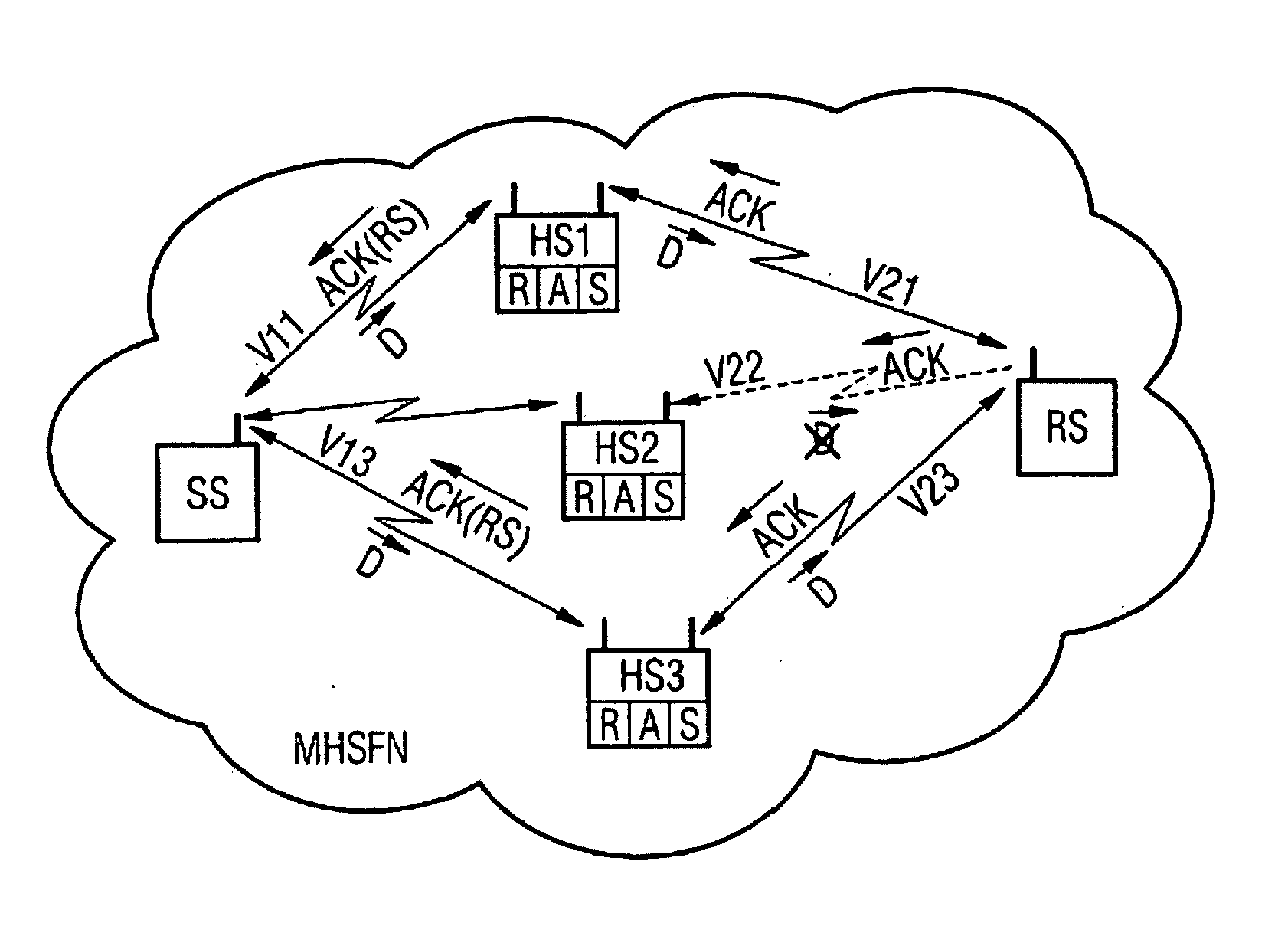
[0021] As can be seen in FIG. 1, an exemplary communication system MHSFN has a multiplicity of mutually communicating stations. Shown as a communication system by way of example is a multi-step or multi-hop (MH) communication system embodied as a single frequency network (SFN). Transmission to other communication systems, in particular to ad-hoc communication systems, is, however, also possible.

[0022] A situation is shown in which a transmitting station SS sends data D to a receiving station RS. The distance between the transmitting station SS and the receiving station RS is here assumed to be too great to allow direct transmission over a direct communication link between the two. The transmitting station SS sends its data D over a multiplicity of communic...


PUM


Abstract

In a method for the error-monitored transmission of data via interfaces of a multi-step communication system, the data is transmitted from a transmitter station to a data-receiving station via at least two relay stations which are connected therebetween and receive and further transmit the data parallel to each other. The data is retransmitted if the transmission has been insufficient due to a request from the receiver end and/or due to the lack of a confirmation from the receiver end. In order to increase performance while reducing power consumption of the system, the request or confirmation is generated only by the receiver station and is sent back to the transmitter station. The relay stations consequently do not generate any confirmations or requests.

Description

CROSS REFERENCE TO RELATED APPLICATIONS [0001] This application is based on and hereby claims priority to PCT Application No. PCT / EP2003 / 006333 filed on Jun. 16, 2003, European Application No. 02013827.7 filed on Jun. 21, 2002, and German Application No. 102 27 852.0 filed on Jun. 21, 2002, the contents of which are hereby incorporated by reference.BACKGROUND OF THE INVENTION [0002] The invention relates to a method for the error-monitored transmission of data over parallel interfaces of a multi-step communication system [0003] In multi-step communication systems, referred to also as multi-hop communication systems, data is transmitted from a transmitting station to an ultimately receiving station either directly or over a multiplicity of intermediate stations or relay stations connected therebetween. As well as being transmitted over a single intermediately connected relay station, the data can also be transmitted over a multiplicity of relay stations connected in series one behind...

Claims


Application Information

Patent Timeline
Patent Type & Authority Applications(United States)
IPC IPC(8): H04L1/00H04L1/16H04L12/701
CPCH04B7/15528H04L1/0054H04L1/08H04L1/16Y02D70/34H04L2001/0097H04W40/12H04W88/04Y02D70/446H04L45/00Y02D30/70H04L45/243
Inventor EICHINGER, JOSEFGIEBEL, TOBIASLAMPE, MATTIASROHLING, HERMANNSCHULTZ, EGONZIRWAS, WOLFGANG
Owner NOKIA SIEMENS NETWORKS GMBH & CO KG
Why Eureka
Try Eureka