
Method of generating a conforming hybrid grid in three dimensions of a heterogeneous formation crossed by one or more geometric discontinuities in order to carry out simulations

a heterogeneous formation and hybrid grid technology, applied in the field of three-dimensional generation of a conforming hybrid grid of a heterogeneous formation crossed by one or more geometric discontinuities in order to carry, can solve the problems of inability to apply the grid technology used in the other fields, inability to simulate reservoirs using finite difference and finite element type methods, and inability to meet the needs of reservoir simulation. , to achieve the effect of reducing the cost of memory, the memory cost involved

Active Publication Date: 2005-12-08
INST FR DU PETROLE
View PDF15 Cites 85 Cited by
  • Summary
  • Abstract
  • Description
  • Claims
  • Application Information

AI Technical Summary

Benefits of technology

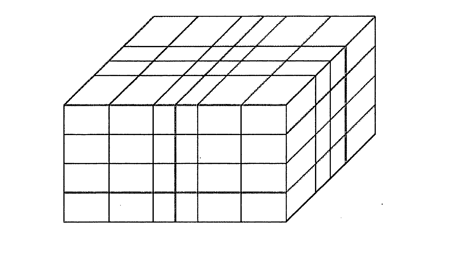
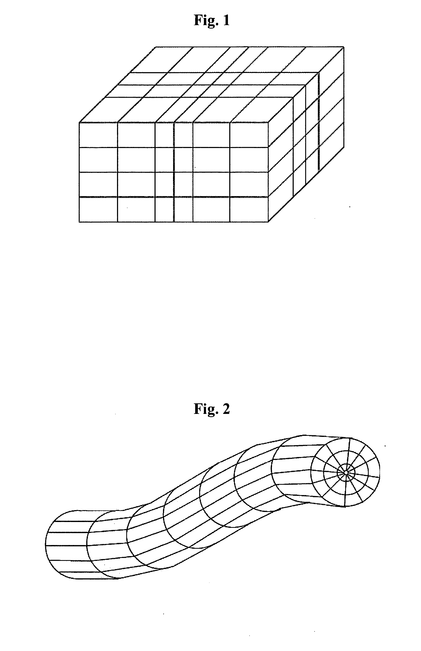
The invention is a method for generating a hybrid grid to represent fluid flows in a heterogeneous medium with geometric discontinuities, such as wells and fractures. The method involves creating a minimum cavity size and constructing a transition grid by taking into account constraints such as conformity, convexity, and self-centering. The numerical scheme used can be a two-point approximation of fluid flows. The invention provides a more accurate and efficient way to model fluid flows in complex geometries.

Problems solved by technology

However, the gridding techniques used in these other fields cannot be applied as they are to the petroleum sphere because the professional constraints are not the same.
The finite difference and finite element type methods are therefore not suited for reservoir simulation, only the finite volume type methods are.
The memory cost involved by the use of an unstructured grid can therefore become very rapidly penalizing.
Structured grids have already shown their limits: their structured nature facilitates their use and implementation, but this also gives them a rigidity that does not allow all the geometric complexities of the geology to be represented.
Unstructured grids are more flexible and they have allowed to obtain promising results but they still are 2.5D grids, i.e. the 3rd dimension is obtained only by vertical projection of the 2D result, and their lack of structure makes them more difficult to use.
However, the use of pyramidal or tetrahedral cells does not allow to use a cell-centered finite volume type method.
Although this 2.5D hybrid grid has allowed to take a good step forward in reservoir simulation in complex geometries, the fact remains that this solution does not allow to obtain an entirely realistic simulation when the physical phenomena modelled are really 3D.
However, none of these methods is really satisfactory: the space created by the cavity does not allow the transition grid to keep an intermediate cell size between the well grid cells and the reservoir grid cells.

Method used


Image

  • Method of generating a conforming hybrid grid in three dimensions of a heterogeneous formation crossed by one or more geometric discontinuities in order to carry out simulations
  • Method of generating a conforming hybrid grid in three dimensions of a heterogeneous formation crossed by one or more geometric discontinuities in order to carry out simulations
  • Method of generating a conforming hybrid grid in three dimensions of a heterogeneous formation crossed by one or more geometric discontinuities in order to carry out simulations

Examples


first embodiment

angulation

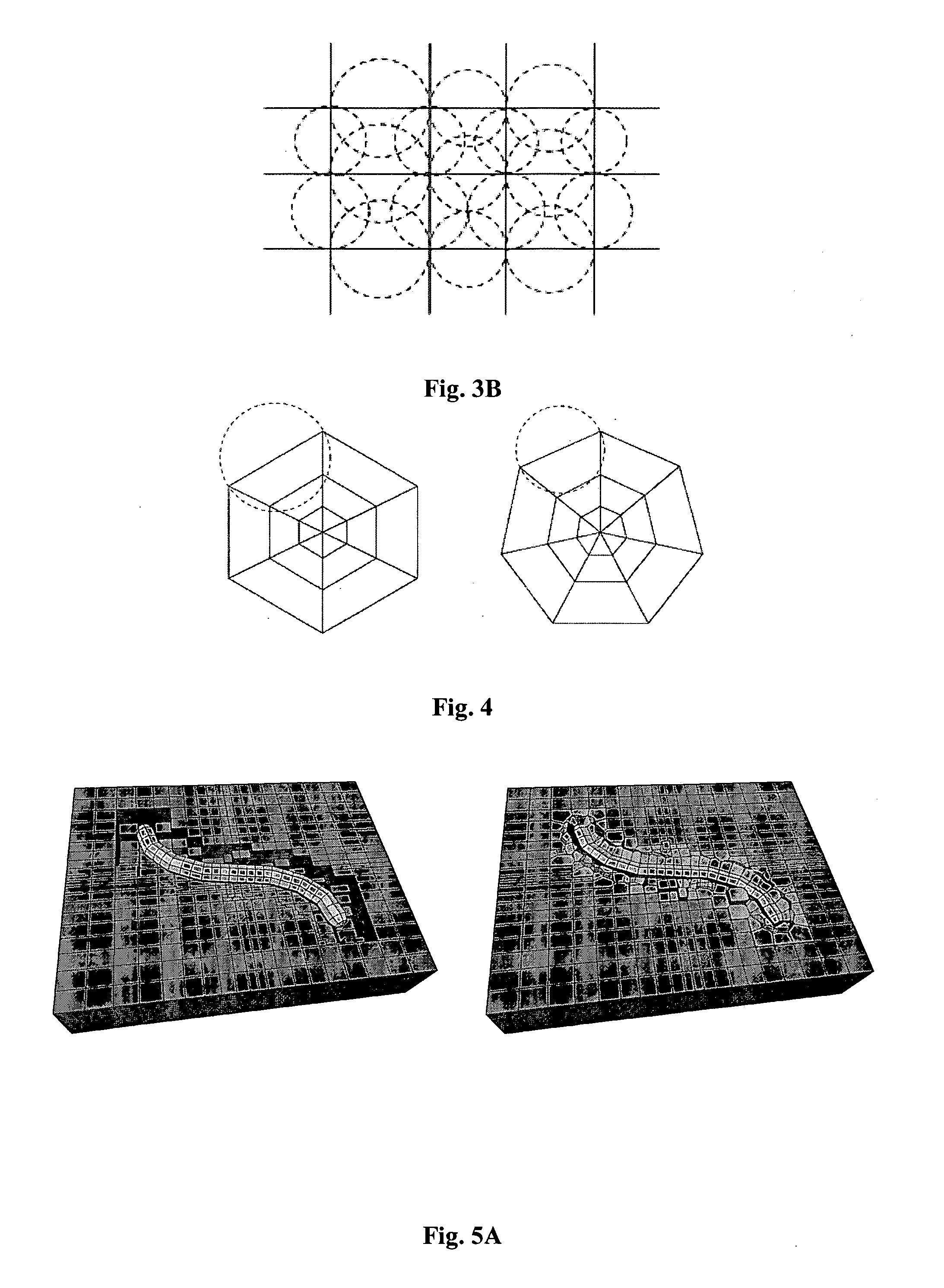
[0133] According to a first embodiment, the method is based on the construction of a Delaunay triangulation of the vertices of the cavity to define the sites of the cavity. This triangulation must be in accordance with the constraints of the cavity made up of quadrilaterals. It is therefore necessary to ensure that each side of the cavity is Delaunay admissible, i.e. that the sides bordering the cavity belong to the Delaunay triangulation of the vertices of the cavity. The cavity is referred to as “Delaunay admissible” if the diametral sphere of each edge of the reservoir cells is empty of any vertex of the well and if the diametral sphere of each edge of the well cells is empty of any vertex of the reservoir (notion of Gabriel cavity). FIGS. 3A and 3B illustrate the Delaunay admissibility of the reservoir grid and of the well grid respectively. FIG. 3B illustrates, on the right, a Delaunay admissible grid and, on the left, a non Delaunay admissible grid. It can be noted t...

second embodiment

tre of the Sphere Circumscribed About a Hexahedron

[0169] In the first embodiment, a Delaunay triangulation of the vertices of the cavity is used to position the sites required for construction of a conforming power diagram between the well and reservoir grids. The sites are defined on the dual edges of the sides of the cavity, so that they are located at an equal distance from the vertices of the associated quadrilateral sides. This distance is different for each site and it is a function of the space present between the boundary of the well and that of the reservoir, which is given locally by the simplexes of the triangulation.

[0170] However, the size of the cavity being known and controlled, each site of the cavity can be directly defined in such a way that the distance between a site and each vertex of the associated constraint sides is the same. The method benefits from the size of the cavity:

δ=δwell+δreservoir

[0171] A)—Determination of P(x,y,z)

[0172] Selection of the Sites ...


PUM


Abstract

Method of generating a hybrid grid, in order to carry out simulations in accordance with a defined numerical scheme, in three dimensions and admissible in the numerical scheme sense, of a heterogeneous formation crossed by one or more geometric discontinuities such as, for example, an underground formation where one or more wells have been drilled, or a fractured formation, by combining structured grids and unstructured grids. The hybrid grid is achieved by associating a first structured grid for gridding the heterogeneous medium with second structured grids for gridding a zone around each discontinuity. A cavity of minimum size, allowing the cells of the transition grid to have an intermediate size between the size of the cells of the first grid and the size of the cells of the second grids, is first generated, entirely automatically. A transition grid meeting the constraints of the numerical scheme used for simulation is then constructed. Finally, the quality of the transition grid is improved by optimizing it under quality controls in the numerical scheme sense, in order to define a perfectly admissible transition grid in the sense of the numerical scheme selected. Applications: hydrocarbon reservoir simulators for example.

Description

FIELD OF THE INVENTION [0001] The present invention relates to a method of generating in three dimensions a hybrid grid of a heterogeneous formation crossed by one or more geometric discontinuities in order to carry out flow simulations for example. [0002] The method applies more particularly to the formation of a grid suited to an underground reservoir crossed by one or more wells, or by fractures or faults, in order to model displacements of fluids such as hydrocarbons. BACKGROUND OF THE INVENTION [0003] During development of a hydrocarbon reservoir, it is essential to be able to simulate gas or oil production profiles in order to assess its cost-effectiveness, to validate or to optimize the position of the wells providing development and production. The repercussions of a technological or strategic change on the production of a reservoir also have to be estimated (location of the new wells to be drilled, optimization and selection during well completion, . . . ). Flow simulation ...

Claims


Application Information

Patent Timeline
Patent Type & Authority Applications(United States)
IPC IPC(8): E21B43/00G01V1/30G06T17/20
CPCG06T17/20
Inventor FLANDRIN, NICOLASBENNIS, CHAKIBBOROUCHAKI, HOUMANLEMONNIER, PATRICK
Owner INST FR DU PETROLE
Learn More