Split key segmental retaining wall system

a technology of segmental retaining walls and key segments, which is applied in the direction of bulkheads/piles, soil preservation, artificial islands, etc., can solve the problems of limited space at the top of the wall, limited use of srw units in their current configuration (battered only), and modularity, and achieves the effect of small width

Active Publication Date: 2005-12-15
JAGNA
View PDF13 Cites 6 Cited by
  • Summary
  • Abstract
  • Description
  • Claims
  • Application Information

AI Technical Summary

Benefits of technology

[0012] It has now been found that the above mentioned problem related to a need for diversity in the construction of a segmented earth retaining wall can easily be solved by using SRW blocks each having a split key tongue, viz. a tongue provided with a splitting groove that allows splitting of the tongue to make it smaller in width, and thus to adjust at will the position of the SRW blocks and thus the shape of the wall to be erected.

Problems solved by technology

If SRW blocks with such an offset tongue and groove system to create a batter or setback to the wall are commonly used, it remains that in design situations, a vertical wall (vs. a setback wall) is more desirable, and therefore, the use of the SRW unit in its current configuration (battered only) is limited.
In some design situations, the space at the top of the wall is limited, either due to property lines, other structures, or simply a desire to maximize the usable land above the wall.
A problem with this kind of SRW system is that depending on the kind of wall to be erected and the kind of inclination to be given to it, the modular, segmental retaining wall blocks may substantially vary in shape and size.
As such, each mould is relatively expensive and may only last for a specific length of time or number of manufacturing cycles.
With each additional mould, there are costs associates with not only the direct purchase of the mould, but also, the manufacturing time lost when chancing moulds, the increased complexity of managing additional components, and the increased complexity of the system in general from a user perspective (education, inventory, etc.).

Method used


Image

  • Split key segmental retaining wall system
  • Split key segmental retaining wall system
  • Split key segmental retaining wall system

Examples


Embodiment Construction

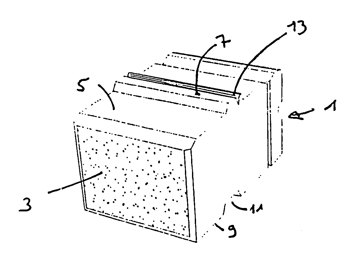
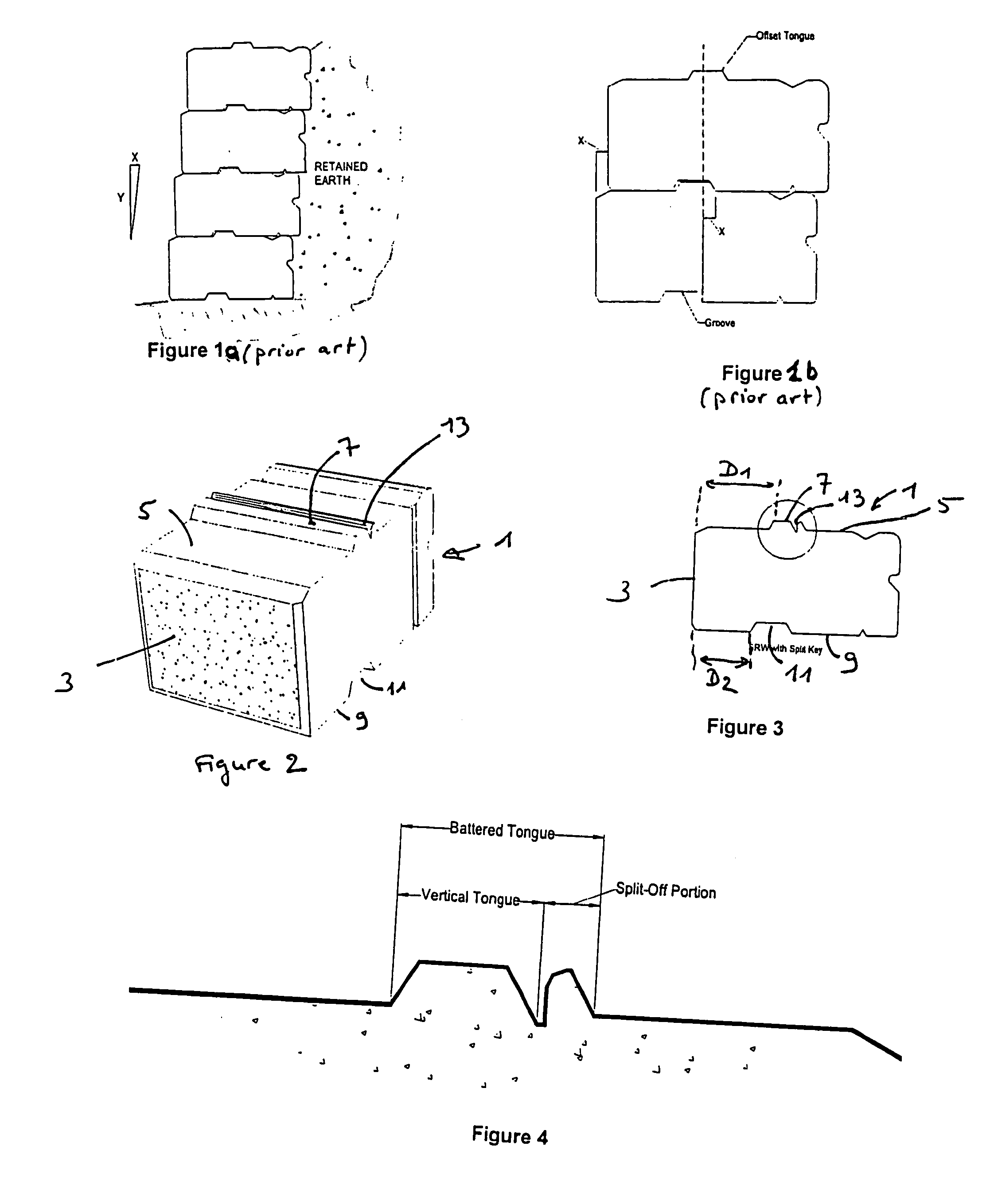
[0037] As clearly shown in FIGS. 2 and 3, the SRW block 1 according to the invention has: [0038] a front side 3; [0039] a top side 5 with a transversal tongue 7 of a given width projecting from it, the tongue 5 extending at a first distance D1 from the front side 3; and [0040] a bottom side 9 with a transversal groove 11 made in it, the groove being sized to receive the tongue 7 of another similar block positioned below and thus to allow stacking of the blocks (see FIGS. 8 and 10), the groove extending at a second distance D2 from the front side that is smaller than the first distance D1.

[0041] As also shown, the first and second distances D1 and D2 are selected so that the tongue 7 and the groove 11 are offset with respect to each other over a distance that is smaller than the width of the tongue 7.

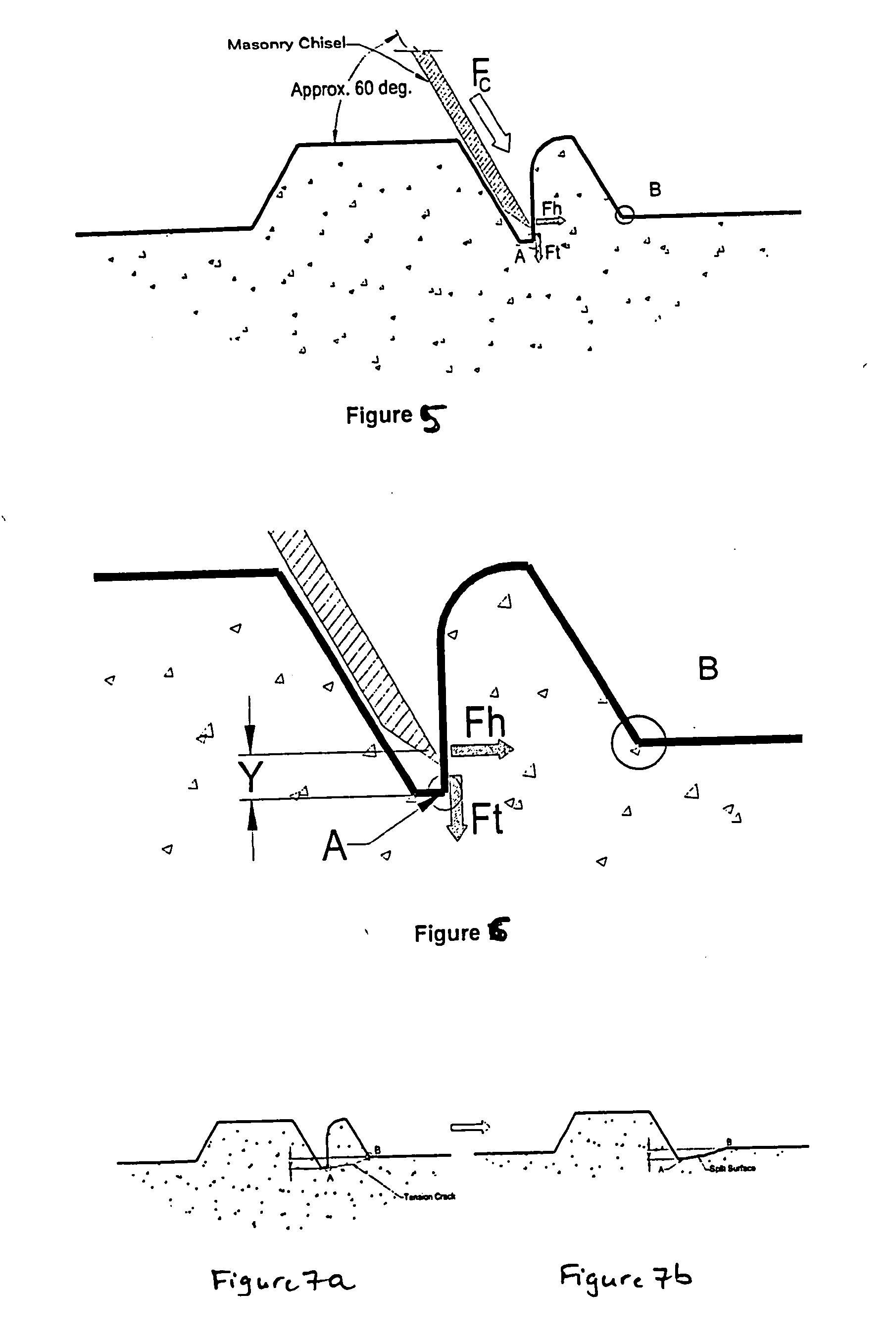
[0042] In accordance with the invention, the tongue 7 is provided with a splitting groove 13 sized and positioned to allow splitting of the tongue 7 with a splitting tool along a trans...


PUM


Abstract

Disclosed is a segmental earth retaining wall block having a front side, a top side with a transversal tongue of a given width projecting from it, the tongue extending at a first distance from the front side, and a bottom side with a transversal groove made in it, the groove being sized to receive the tongue of another similar block positioned below and thus to allow stacking of the blocks. The groove extends at a second distance from the front side that is smaller than the first distance, and the first and second distances are selected so that the tongue and the groove 11 are offset with respect to each other over a distance that is smaller than the width of the tongue. Advantageously, the tongue is provided with a splitting groove sized and positioned to allow splitting of the tongue with a splitting tool along a transversal line that is positioned to permit the remaining portion of this tongue to fit into the groove of a further similar block stacked on top of the present block with the front side of this further similar block extending in a same vertical plane as the first side of the present block. As a result, one may stack the above mentioned blocks as such, the resulting wall being then battered, or one may stack the above mentioned blocks after having splitted their tongues, the resulting wall being then vertical.

Description

FIELD OF THE INVENTION [0001] The present invention relates to an improved segmental retaining wall system. [0002] More particularly, the invention relates to a segmental retaining wall (SRW) system wherein each stackable block (also called “units”, “SRW units” or “SRW blocks” hereinafter) is provided with a tongue with a splitting groove that allows the user to construct either a battered (inclined) or vertically aligned segmental retaining wall with the same unit. BRIEF DESCIRPTION OF THE PRIOR ART [0003] Segmental earth retaining walls are a category of earth retention system that utilize modular, dry stacked (no mortar), preliminary-cast concrete blocks to create a stable mass with sufficient weight to resist earth pressures developed by the adjacent soil. [0004] In this field, it is of common practice to use segmental modular earth retaining wall blocks with a groove on their bottom side and a tongue on their upper side which are offset with respect to each other to allow “auto...

Claims


Application Information

Patent Timeline
Patent Type & Authority Applications(United States)
IPC IPC(8): E03F3/06E04B2/02E02D29/02E04C1/39
CPCE02D29/025E04B2002/0208E04C1/395
Inventor RISI, ANGELO
Owner JAGNA
Why Eureka
Try Eureka