Throttle control device for internal combustion engines

a control device and internal combustion engine technology, applied in the direction of electric control, idling devices, charge feed systems, etc., can solve the problems of pid control gain and difficulty in controlling the motor torque, so as to achieve optimal controllability, reduce power consumption, and retain control stability

Inactive Publication Date: 2005-12-15
MITSUBISHI ELECTRIC CORP
View PDF6 Cites 6 Cited by
  • Summary
  • Abstract
  • Description
  • Claims
  • Application Information

AI Technical Summary

Benefits of technology

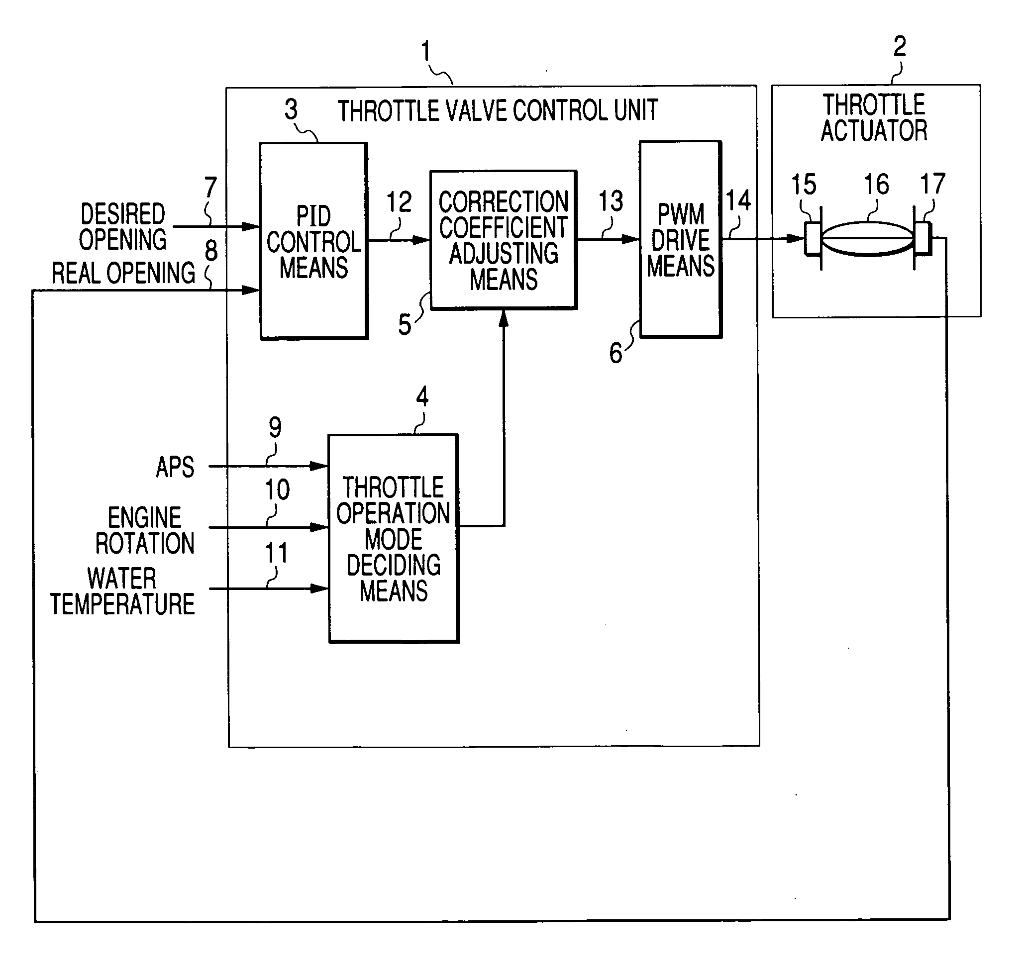
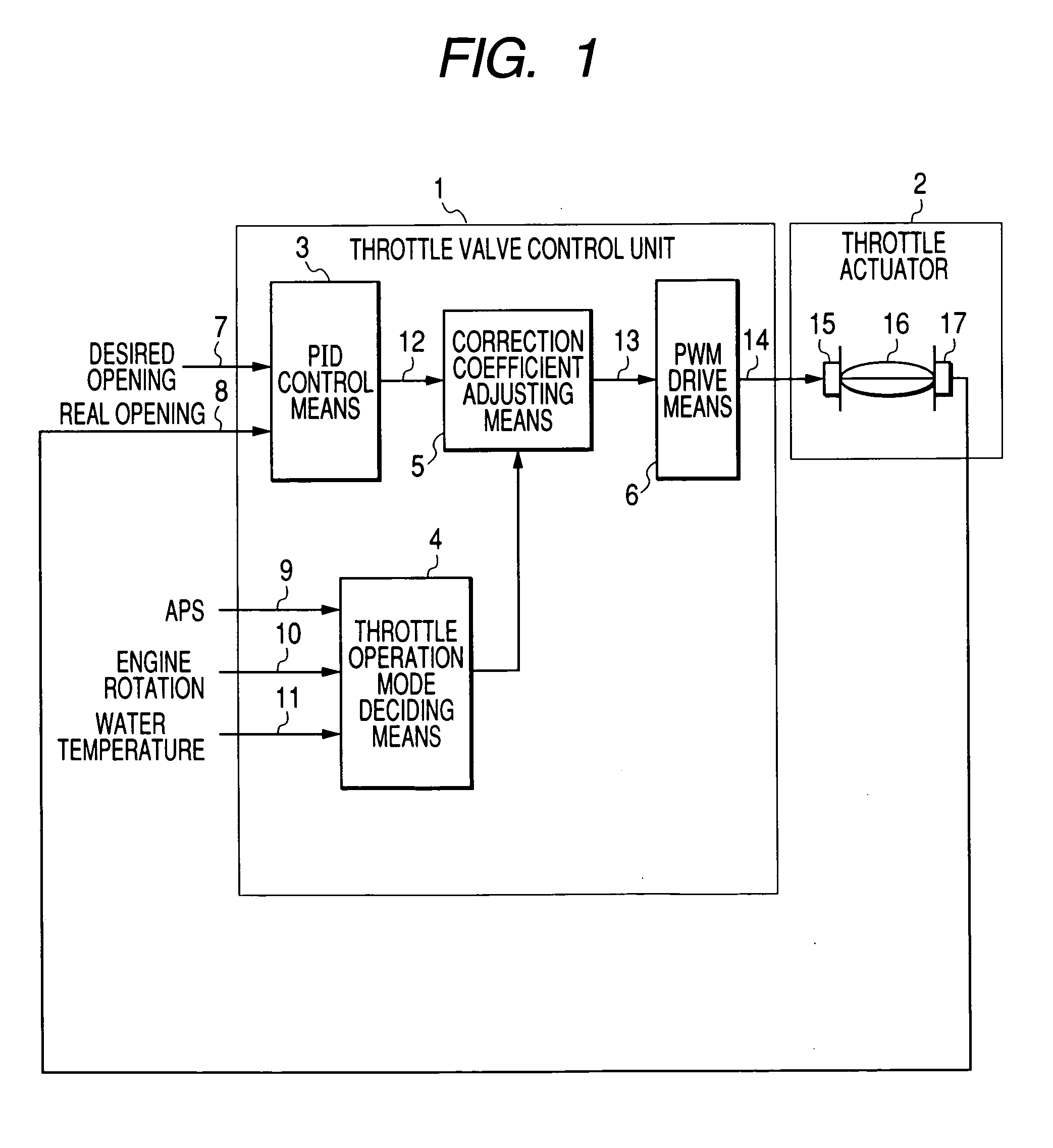
[0010] According to a first aspect of the invention, there can be provided a throttle valve control device of an internal combustion engine for controlling the opening of a throttle valve by the operation of an accelerator pedal, comprising: a throttle valve; a drive motor for the throttle valve; a throttle opening sensor for detecting the real opening of the throttle valve; feedback control means for outputting an amount of activation for activating the drive motor by using a predetermined control gain so that the real opening of the throttle valve detected by the throttle opening sensor may be identical to either a desired opening based on at least the depression of the accelerator pedal or a desired opening at an ISC time based on at least the speed of the internal combustion engine; throttle operation mode deciding means for deciding the operation mode of the throttle valve and correction coefficient adjusting means for correcting the activation amount outputted from the feedback control means with a predetermined correction coefficient on the basis of the decision result of the throttle operation mode deciding means. The throttle control device of the invention is capable of performing a correction processing with a simple configuration of a process logic and at an appropriate manner, and enables to make compatible the quick response of the real opening and the stability of the control at the time of change of a desired opening, thereby attaining an optimum controllability.
[0011] According to a second aspect of the invention, moreover, the correction coefficient is changed by the correction coefficient adjusting means into a first predetermined correction coefficient, in case the throttle operation mode other than the ISC running time after the warm-up is decided by the throttle operation mode deciding means, and into a predetermined second correction coefficient in the throttle operation mode other than the aforementioned one, so that the activation amount outputted from the feedback control means is corrected and outputted. In the operation other than the ISC running time after the warm-up, therefore, the activation amount outputted from the feedback control means is directly outputted with the first correction coefficient (=1.0), to avoid the unnecessary correction at the time when the minute opening deviation occurs, thereby to reduce the power consumption and retain the control stability. At the ISC running time after the warm-up, the response delay, as might otherwise be caused by the drive torque shortage due to the increase in the winding resistance at the high temperature of the DC motor, is avoided by the second correction coefficient even when the minute opening deviation occurs. Thus, it is possible to provide a throttle control device for an internal combustion engine, which can make compatible the quick response of the real opening and the stability of the control.
[0012] According to a third aspect of the invention, moreover, the throttle operation mode deciding means makes the decision on the basis of at least the depression amount of the accelerator pedal and the cooling water temperature of the internal combustion engine. Thus, it is possible to provide a throttle control device for an internal combustion engine, which can decide the ISC running state at the ISC running time of the internal combustion engine especially after the warm-up and can correct the activation amount of the throttle actuator according to the operation mode of the throttle valve, as set according to the running state of the engine, thereby to provide a throttle control device which can make compatible the quick response of the real opening and the stability of the control when the desired opening changes.
[0013] According to a fourth aspect of the invention, moreover, the adjustment of the correction coefficient by the correction coefficient adjusting means makes a gradual change at the changing time from the first correction coefficient to the second correction coefficient, and makes a quick change at the changing time from the second correction coefficient to the first correction coefficient. As a result, the control disturbance due to the abrupt increase in the DUTY value at the time when the running state shifts to the ISC running after the engine warm-up can be suppressed to avoid the unnecessary correction at the shifting time to the running state other than the ISC running after the warm-up, thereby to provide a throttle control device which can make compatible the quick response and the control stability.
[0014] According to a further aspect of the invention, moreover, the second correction coefficient is learned and corrected by the responding operation of the real opening. Thus, it is possible to provide a throttle control device for an internal combustion engine, which can achieve a stable controllability even against the individual difference of the throttle actuator.

Problems solved by technology

It is, therefore, difficult to control the motor torque such that the throttle valve is quickly driven when a minute opening deviation occurs in the entire temperature range of the throttle valve operation and such that the real opening may not overshoot or undershoot from the desired opening.
This raises a problem that the PID control gain generally has to be adapted for avoiding the opening hunting at the low temperature while sacrificing the opening responsiveness at the high temperature.

Method used


Image

  • Throttle control device for internal combustion engines
  • Throttle control device for internal combustion engines
  • Throttle control device for internal combustion engines

Examples


embodiment 2

[0033] In Embodiment 1 thus far described, the second correction coefficient DC2 is fixed. In Embodiment 2, on the other hand, the base value DC2 of the second correction coefficient is learned and corrected (by ΔDC2) on the basis of the response results of the real opening to the desired opening change at the ISC running time after the internal combustion engine was warmed up, so that a second learned correction coefficient value DCL2 is set.

[0034] The operations to learn the second correction coefficient will be described with reference to the flow charts of the learning procedures of the correction coefficient of FIG. 5 and FIG. 6. Here, letter A of FIG. 5 indicates an advance to A of FIG. 6. At Step S100 of FIG. 5, it is decided by the throttle operation mode deciding means 4 whether or not the internal combustion engine is in the ISC running mode after the warm-up. If this answer is No, the routine is ended. In case it is decided that the internal combustion engine is in the I...


PUM


Abstract

A throttle control device having a quick response and a control stability in the ISC running mode of an internal combustion engine comprises: feedback control means for outputting an amount of activation for activating a drive motor by using a predetermined control gain such that the real opening of a throttle valve detected by a throttle opening sensor for detecting the real opening of the throttle valve may be equalized to either a desired opening based on at least the depression of the accelerator pedal or a desired opening at the ISC time based on at least the speed of the internal combustion engine; and correction coefficient adjusting means for correcting the activation amount outputted from the feedback control means, with a predetermined correction coefficient on the basis of the decision result of a throttle operation mode deciding means for deciding the operation mode of the throttle valve.

Description

BACKGROUND OF THE INVENTION [0001] 1. Field of the Invention [0002] This invention relates to a throttle control device for an internal combustion engine, in which the real opening of a throttle valve disposed in the intake air passage of the internal combustion engine is feedback-controlled to a desired opening. [0003] 2. Description of the Related Art [0004] The disclosure of JP-A-7-293284 is enumerated as the throttle control device for an internal combustion engine, which is known in the related art. The control device, as disclosed in the Publication, uses the known PID (Proportion Integration differentiation) control arithmetic procedure basically as the control arithmetic processing for feedback (F / B) controlling the real opening of the throttle valve to a desired opening. In order to obtain the amount of activation for a quick valve drive even when the opening deviation (i.e., the desired opening—the real opening) of the real opening to the desired opening is small, moreover...

Claims


Application Information

Patent Timeline
Patent Type & Authority Applications(United States)
IPC IPC(8): F02D41/16F02D41/00F02D35/00F02D11/10F02D41/06F02D9/00F02D9/02F02D45/00
CPCF02D11/105F02D35/0007F02D41/06F02D2041/1409F02D2200/0404
Inventor WATANABE, SHINJI
Owner MITSUBISHI ELECTRIC CORP
Why Eureka
Try Eureka