
Digester wash extraction by individual screen flow control

a technology of individual screen and wash, which is applied in the direction of continuous pulping process, finely divided material pretreatment, papermaking, etc., can solve the problems of difficult to predict and/or control the uniform flow of recirculation flow or free liquor, non-uniform cooking, and non-uniform retention of lignin on individual fibers, so as to avoid total plugging of the screen, maximize energy efficiency, and wash efficiency and chip mass

Active Publication Date: 2005-12-15
INT PAPER CO
View PDF1 Cites 9 Cited by
  • Summary
  • Abstract
  • Description
  • Claims
  • Application Information

AI Technical Summary

Benefits of technology

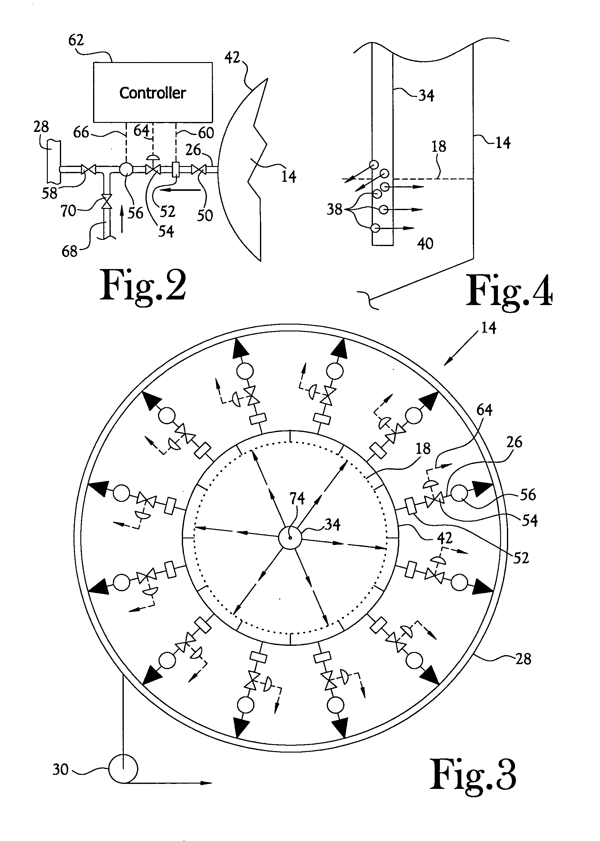
The present invention provides a system for efficiently distributing liquor in a digester system. The invention includes individual temperature, flow measurement, and flow control valves for each wash screen to maximize energy efficiency, wash efficiency, and chip mass. The system also includes a central downcomer with side discharge ports to create a layer of filtrate liquor flowing perpendicularly from the center of the digester toward all the screens. The system also includes automatic or manual back flush apparatus to assist in clearing a screen that is showing signs of plugging. Finally, reducing the wash zone free liquor upflow or establishing a free liquor downflow provides improved uniformity of the product leaving the wash zone.

Problems solved by technology

Because of the nature of the compaction of the chip column, it is difficult to predict and / or control the uniform flow of re-circulation flows or free liquor upflows or downflows through the chip mass in a large diameter continuous digester of the prior art.
Cook non-uniformity across the column profile, with accompanying non-uniform retention of lignin on the individual fibers is a common deficiency of known prior art digesters.
This results in poor displacement and diffusion of dissolved solids (poor wash efficiency) in the chip mass to the wash screens and poor heat transfer in some portions of the chip column.
The poor wash efficiency causes downstream problems in the brown stock treatment and bleaching processes.
The poor heat transfer in the chip column at the bottom of the digester increases the energy costs in these two affected process areas.
Also, during operation, individual wash screens tend to plug off completely with the other screens picking up the flow.
Continuous digesters are only shut down for maintenance on an annual basis, due to cost of such shutdowns.
The chip column adjacent to plugged wash screens leads to poor wash efficiency and poor heat transfer.
There is no known current method to control the individual wash screen flow and temperature in order to break up the pattern of path of least resistance flow of cold blow wash filtrate.
Further, there is currently no known method to unplug the wash screens other than when the digester is empty during the annual shut down.
The upflow through the wash zone is operated at higher than optimum for alkali and temperature profile uniformity because of the current inability to manage and maintain an acceptable wash efficiency in the bottom of the digester.
There is no known current method for adjusting the amount of free liquor upflow through the wash zone in order to maintain uniformity of temperature and alkali in the wash zone where the highest percentage of the cook (time at temperature) is completed with the highest potential for product non-uniformity to be affected.
Whereas this higher free liquor upflow helps to manage the dissolved solids level in the digester discharge, such flow has a negative impact on the temperature and alkali profiles in the wash zone.

Method used


Image

  • Digester wash extraction by individual screen flow control
  • Digester wash extraction by individual screen flow control
  • Digester wash extraction by individual screen flow control

Examples


Embodiment Construction

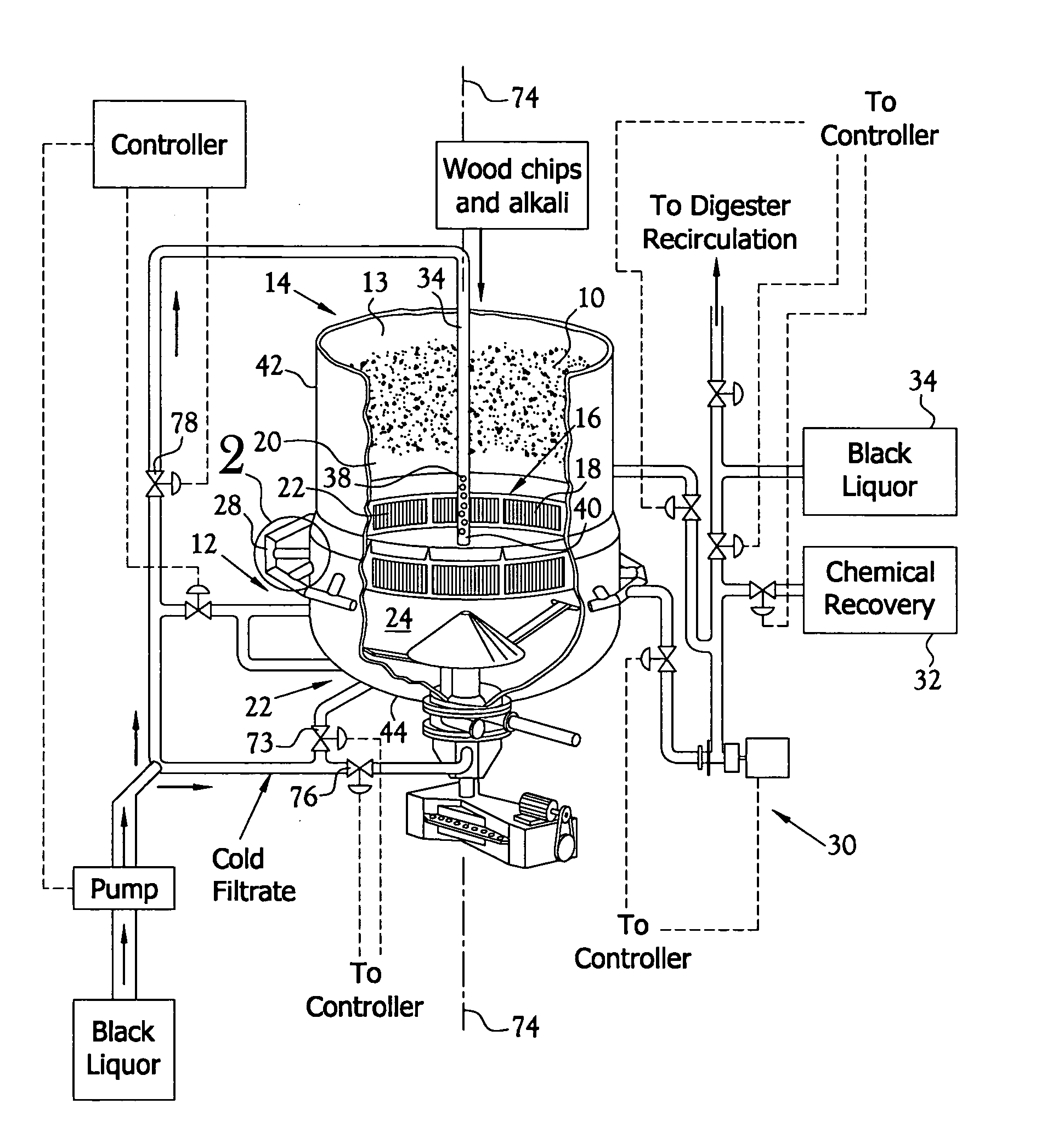
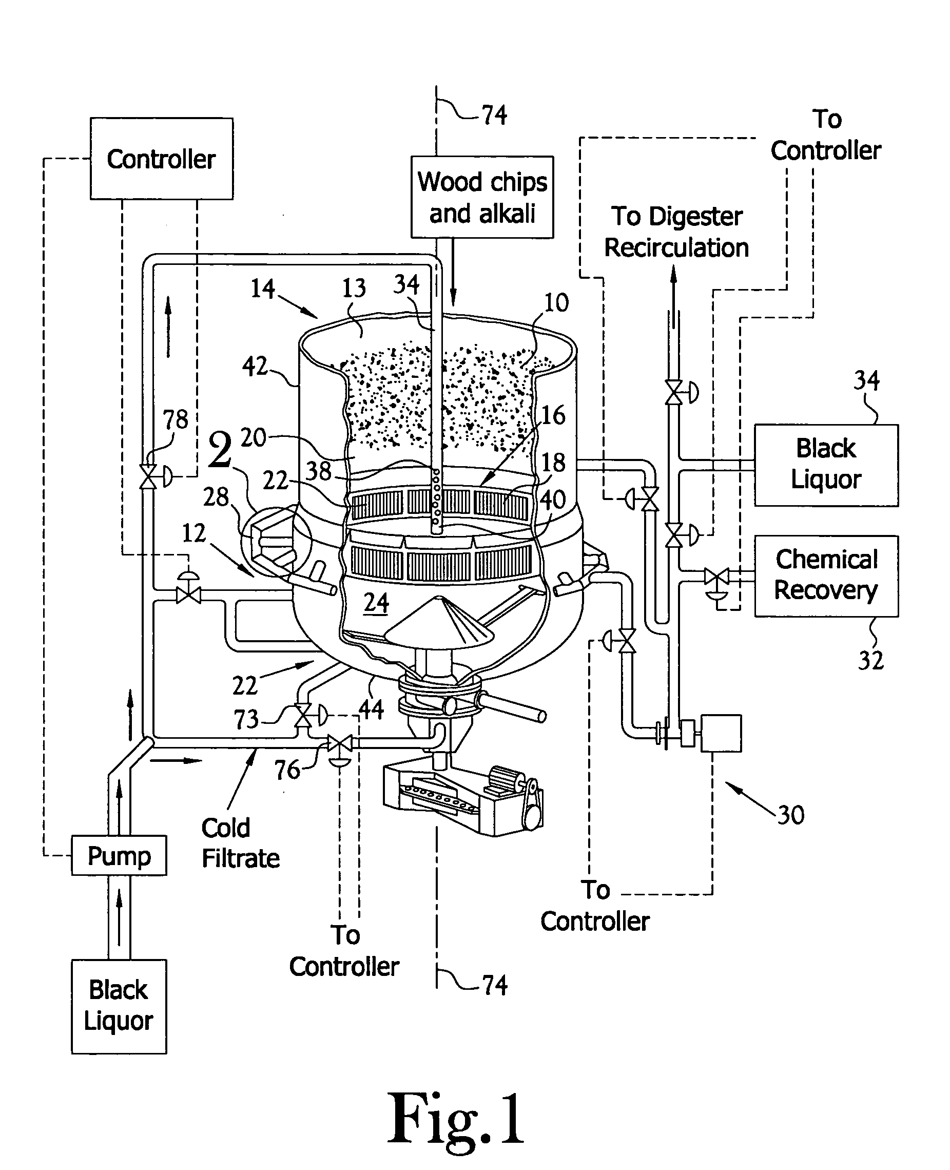
[0021] In the embodiment of the present invention depicted in FIGS. 1 and 2, as noted hereinabove, approximately 50% of the organic chip mass 10 is dissolved in the cooking liquor. The depicted digester 14 includes an upper zone 13 into which the chip mass is loaded. This is an extension of the cooking zone. A set 16 of screens, twelve screens 18 in a typical embodiment, are disposed about the inner circumferential wall 20 of the digester at a location just below the cooking zone 13 and above a wash zone 24 which is disposed at the bottom end of the digester.

[0022] Liquor containing dissolved solids is extracted from the interior of the digester through the screens. The liquor extracted through the individual screens is conveyed to a discharge header 28 which encircles the girth of the digester externally of the digester in the region of the screens and is conveyed, as by a pump system 30, to a chemical recovery station 32 or is selectively returned in part to the digester via a do...


PUM

PropertyMeasurementUnit
diameteraaaaaaaaaa
diameteraaaaaaaaaa
heightaaaaaaaaaa

Abstract

This invention is directed to a method for cooking wood chips in a digester for the separation of wood fibers from their bonded state, the digester having a vertical centerline, a substantially circular cross-section, and a wash zone adjacent the bottom end thereof and a plurality of individual wash screens disposed about the inner wall of the digester for the withdrawal of liquor from the wash zone. In the first step of the method, substantially equal volumes of liquor are dynamically withdrawn from the wash zone through individual ones of the wash screens, while monitoring of the flow rate of liquor exiting the digester through individual ones of the wash screens. The monitored flow rate is used to increase or decrease the flow rate from screens to a value substantially equal to the flow rate of liquor from the digester through each of the screens. As a result, the total volume of liquor exiting the digester through the screens is divided into equal volumes flowing from the wash zone of the digester through each of the wash screens. The equal volumes were extracted substantially simultaneously in a flow direction substantially radially of the digester about substantially the entire circumference of the digester and within a plane disposed substantially perpendicular to the vertical axis of the digester.

Description

CROSS-REFERENCE TO RELATED APPLICATIONS [0001] Not Applicable STATEMENT REGARDING FEDERALLY SPONSORED RESEARCH OR DEVELOPMENT [0002] Not Applicable FIELD OF INVENTION [0003] This invention relates to continuous digesters for wood chips in the papermaking industry. BACKGROUND OF INVENTION [0004] As commonly practiced in the prior art relating to papermaking, wood chips and alkali liquor (white liquor) are pumped into the top of a hydraulic cooking vessel (digester, approximately 180 feet high and approximately 23 feet in diameter) that is operated at high pressure (165 psig) and temperature (325 degrees F.). A chip cooking process proceeds over the time that it takes the saturated chip column to move down through the digester where the discharge rate of the chips to a blow line at the bottom of the digester is matched to the feed rate at the top so as to maintain a constant level and retention time of the chips in the digester. [0005] In the cooking process (delignification of wood c...

Claims


Application Information

Patent Timeline
Patent Type & Authority Applications(United States)
IPC IPC(8): D21C3/24D21C7/00D21C7/12D21C7/14
CPCD21C3/24D21C7/12D21C7/14
Inventor LAWRENCE, DEAN KENNETHHILL, WAYNELUDWIG, STANISLAUS LEOCODE, DAVID RICHARD
Owner INT PAPER CO
Learn More