Method for revamping fixed-bed catalytic reformers

a technology of catalytic reformers and fixed beds, which is applied in the field of catalytic reformers to achieve the effect of avoiding major expense, improving reformate quality and yield

Inactive Publication Date: 2005-12-15
EXXON RES & ENG CO
View PDF13 Cites 39 Cited by
  • Summary
  • Abstract
  • Description
  • Claims
  • Application Information

AI Technical Summary

Benefits of technology

[0011] The present invention relates to a scheme for converting fixed-bed, catalytic reformer units to units with moving bed reactors. It differs from the scheme described in US 2004 / 0129605 A1 in that it makes use of existing reactor vessels; in the present case, these vessels are placed into new service, this time for catalyst regeneration. Because this conversion scheme requires only new reactors, it avoids the major expense connected with the provision of a moving bed regenerator and so presents an economically favorable case for conversion to moving bed reactor operation. The costs of conversion associated with the present conversion technique will be significantly less than conversions in which both the reactors and the regenerators are converted to moving bed operation because the present conversion technique makes use of existing facilities in addition to making new use of the reactor vessels while, at the same time, not requiring dedicated onsite continuous catalyst regeneration facilities. One advantage of the present conversion scheme is that the full advantages of moving bed reactor operation are secured with the reactors operated at the lower pressures characteristic of continuous operation so as to improve reformate quality and yield.

Problems solved by technology

The conversion scheme may, however, be also applied to existing semi-regenerative units although here with the marginal economic disadvantage of having to provide a new regeneration circuit.

Method used


Image

  • Method for revamping fixed-bed catalytic reformers

Examples


Embodiment Construction

[0015] The present invention provides a substantially lower cost option for refiners to make significant improvements to the performance and service factor of existing fixed-bed reformer units. Non-continuous (or fixed-bed) catalytic reformers which can be subjected to the present conversion scheme could be semi-regenerative catalytic reformers or swing-reactor (also referred to as cyclic regeneration) reformers or hybrid systems (with both fixed and moving bed sections), all of which are known.

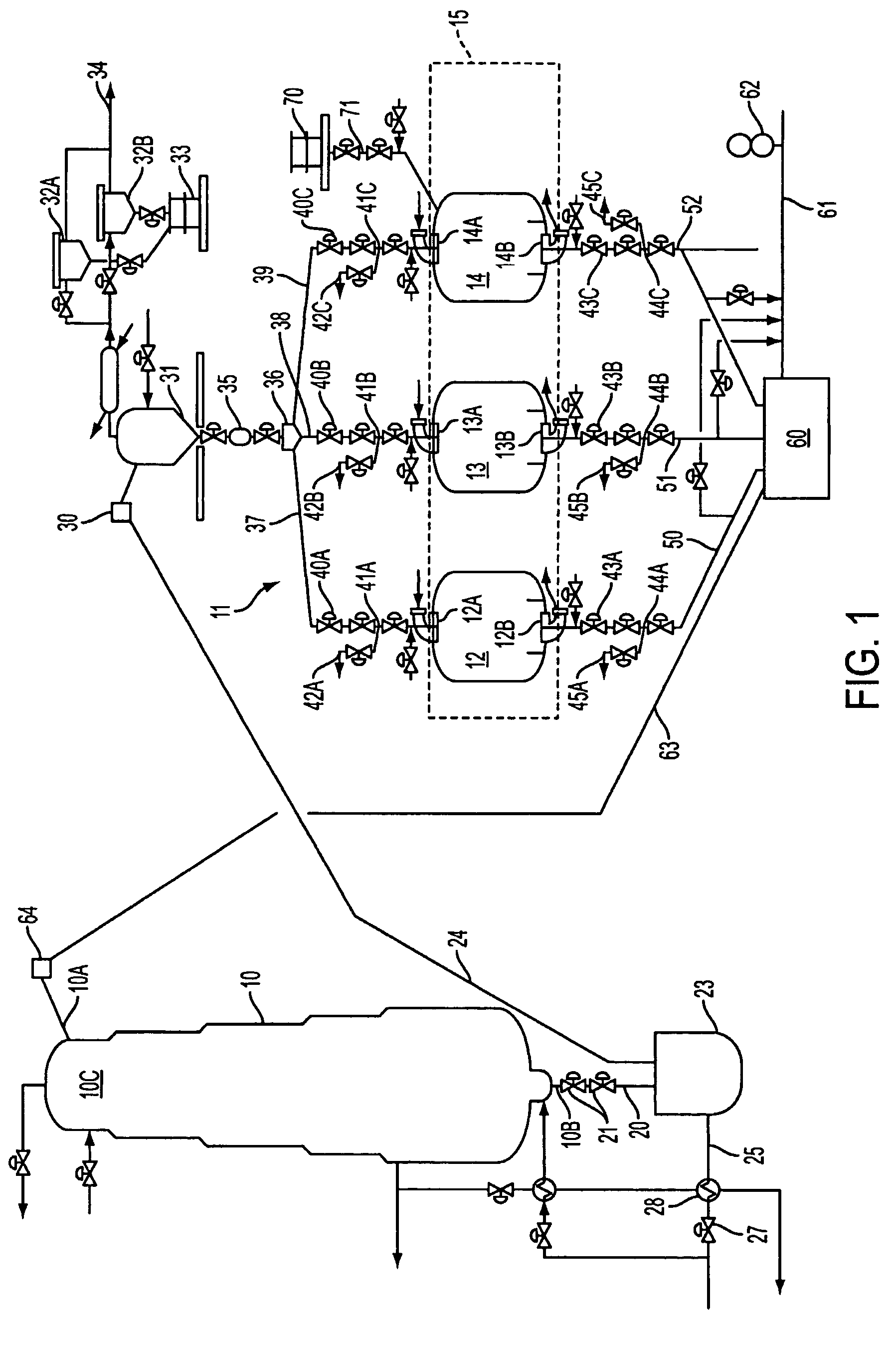
[0016] The present conversion scheme is best adapted to the conversion of cyclic reformer units because the required catalyst regeneration equipment will already be in place and can be applied directly to the new service: the compressors, furnace, chemical injection facilities as well as piping, valving and manifolding can be used without substantial modification to the mode of cyclic regeneration used in the converted unit. Cyclic, fixed-bed reformers have been well-known. In units of this ...


PUM

PropertyMeasurementUnit
swing timeaaaaaaaaaa
pressureaaaaaaaaaa
acid functionalityaaaaaaaaaa

Abstract

A fixed-bed catalytic reformer unit is converted to moving bed reactor/cyclic regenerator operation by re-using the fixed bed reactors of the original unit as regenerator vessels operated in cyclic regeneration mode in a new catalyst regeneration section. A flow connection, suitably a liftpipe, is provided to convey spent catalyst from the spent catalyst outlet of a new moving bed reactor section to the converted regenerator section, together with a flow connection for regenerated catalyst from the regenerator section to the regenerated catalyst inlet of the new moving bed reactor section. A flow control distributor directs spent catalyst sequentially to each of the regenerator vessels to carry out the regeneration with regeneration gas. Each regenerator vessel is cycled through a fill, regeneration, discharge sequence to maintain a continuous flow of catalyst to and from the reactor section.

Description

CROSS REFERENCE TO RELATED APPLICATION [0001] This application relates to a method of converting or revamping fixed bed catalyic reformers to moving bed reactor operation and, as such, is related to US 2004 / 0129605 A1, published Jul. 8, 2004, which described a different conversion scheme. [0002] This application claims the benefit of U.S. Ser. No. 60 / 564,133 filed Apr. 21, 2004.FIELD OF THE INVENTION [0003] The invention relates generally to catalytic reformers. More particularly, the invention relates to an improved method for converting or revamping high pressure, fixed-bed catalytic reformers to catalytic reformers with continuous, moving-bed reactors. BACKGROUND OF THE INVENTION [0004] Catalytic reforming is an established petroleum refinery process. It is used for improving the octane quality of hydrocarbon feeds. Generally, reforming refers to the total effect of molecular changes on a hydrocarbon feed, produced by a number of reactions. Typical reforming reactions include deh...

Claims


Application Information

Patent Timeline
Patent Type & Authority Applications(United States)
IPC IPC(8): B01J8/08C10G35/12C10G49/00C10G59/02
CPCB01J8/12C10G35/12C10G49/002C10G59/02
Inventor GOLDSTEIN, STUART S.VIETS, JOHN W.FIUTOWSKA, BOZENA M.FOJTASEK, BRIAN D.THURTELL, JOHN H.MARSHALL, GREG A.MELLI, TOMAS R.IACCINO, LARRY L.GRAZIANI, KENNETH R.
Owner EXXON RES & ENG CO
Why Eureka
Try Eureka