
Power conversion apparatus and methods using an adaptive waveform reference

a power conversion apparatus and waveform technology, applied in adaptive control, emergency power supply arrangements, instruments, etc., can solve problems such as loop instability, and achieve the effects of stable initial operating state, stable operation, and optimization of current waveform performan

Inactive Publication Date: 2005-12-15
EATON INTELLIGENT POWER LTD
View PDF24 Cites 41 Cited by
  • Summary
  • Abstract
  • Description
  • Claims
  • Application Information

AI Technical Summary

Benefits of technology

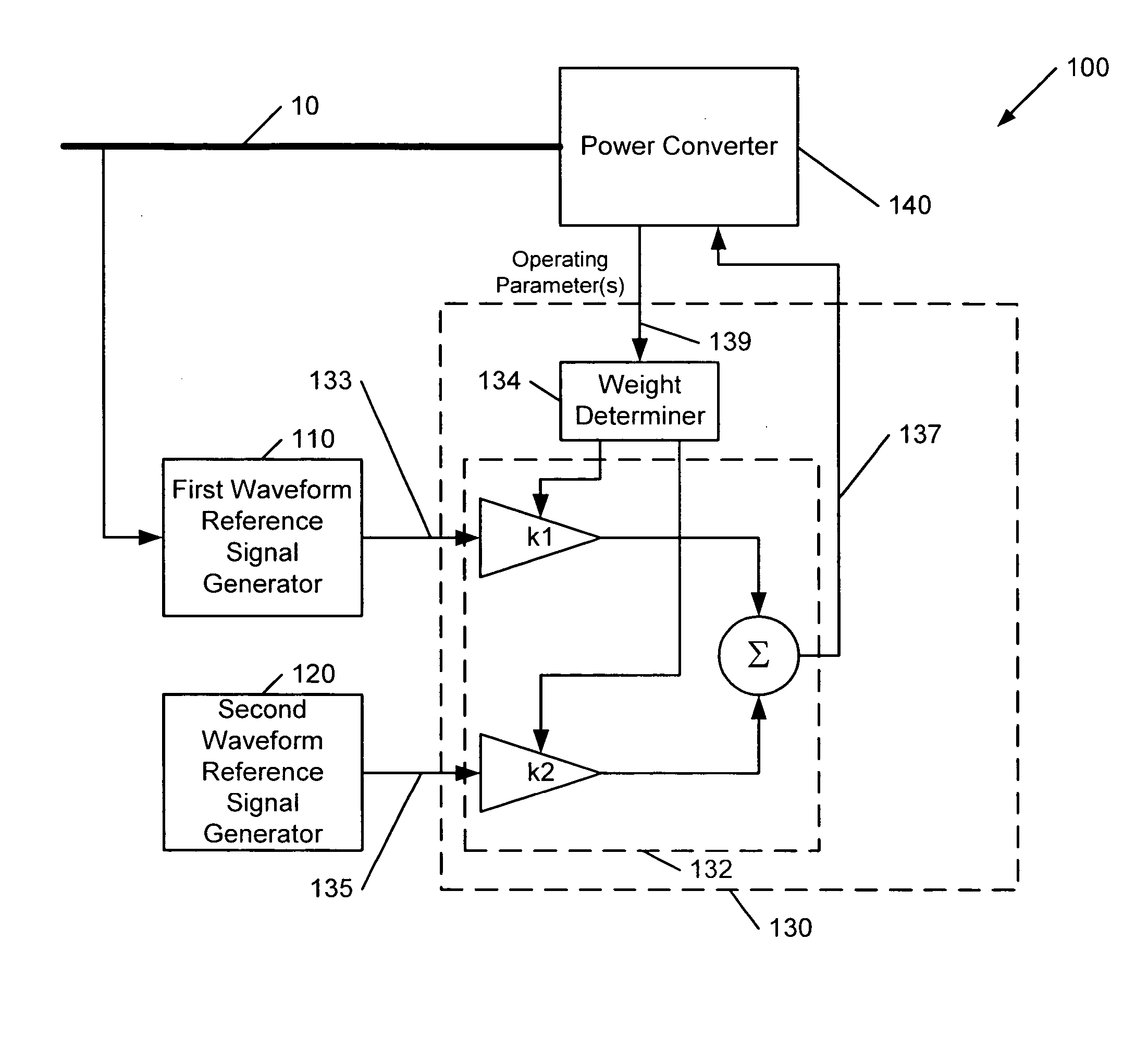
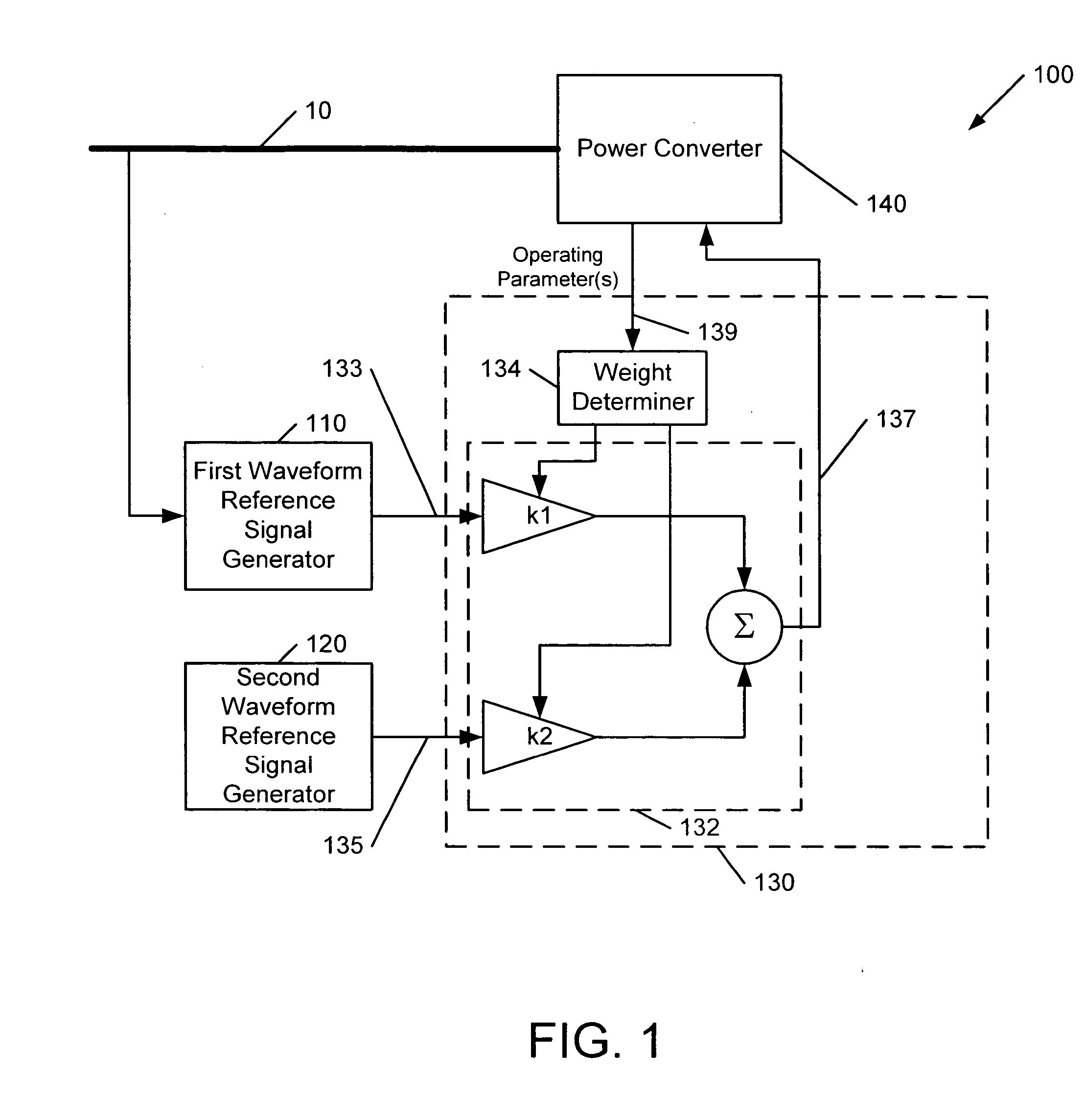
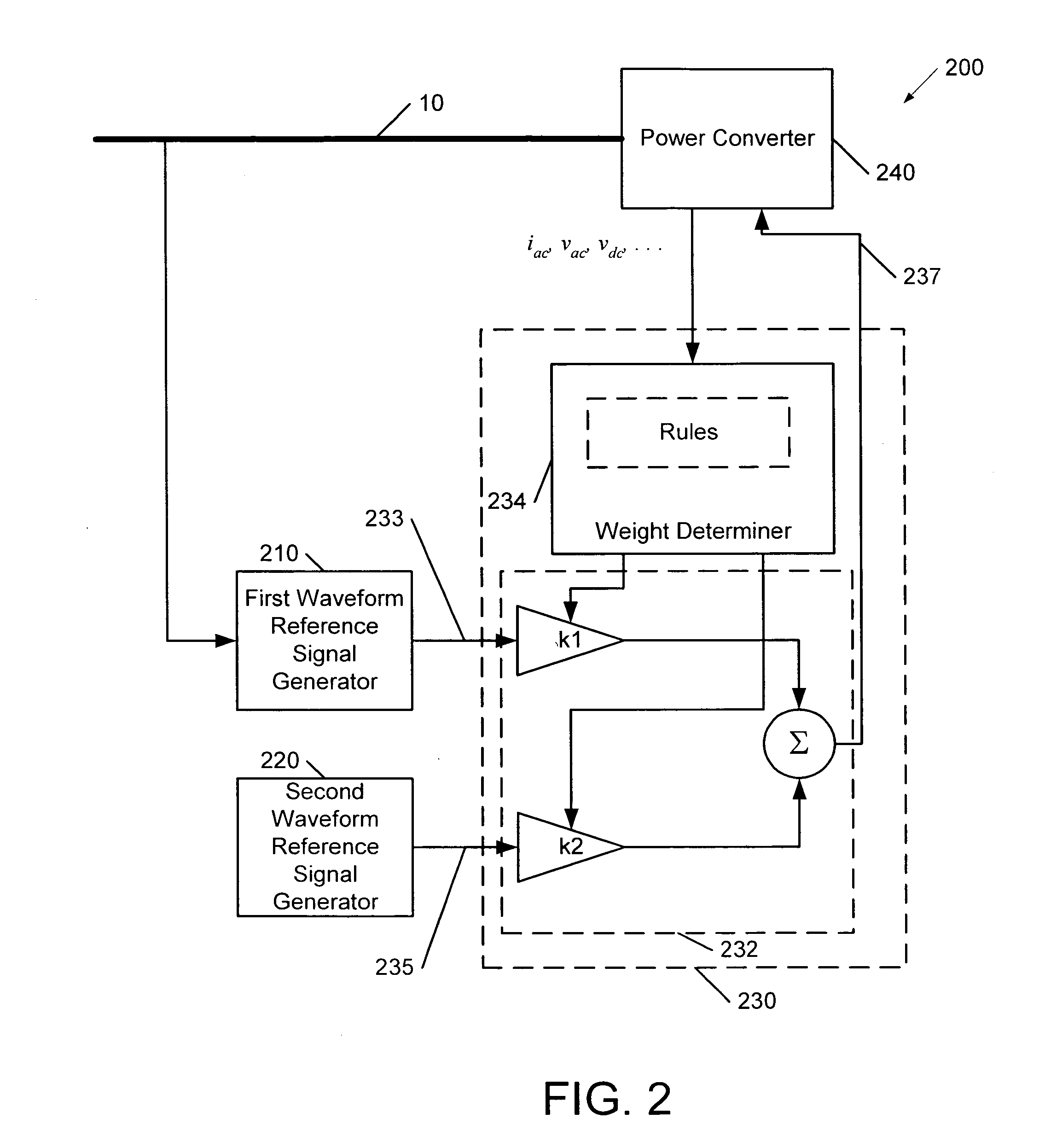
[0007] Embodiments of the invention can provide various benefits. In some rectifier applications, for example, use of a composite waveform reference derived from the AC bus voltage and a sinusoidal reference can allow a power converter to stably operate over a wide range of input conditions while optimizing current waveform performance. In some embodiments, using a source impedance determination to generate an initial weighting of two waveform reference sources can allow a stable initial operating state to be attained, such that reference optimization based on waveform parameters, such as power factor, voltage distortion or harmonic current, can proceed.

Problems solved by technology

However, coupling of such a high bandwidth rectifier to a relatively high impedance source, such as a motor-generator set, can cause an input pole frequency of the rectifier to fall within the current loop bandwidth, which can lead to loop instability.

Method used


Image

  • Power conversion apparatus and methods using an adaptive waveform reference
  • Power conversion apparatus and methods using an adaptive waveform reference
  • Power conversion apparatus and methods using an adaptive waveform reference

Examples


Embodiment Construction

[0013] Specific exemplary embodiments of the invention now will be described with reference to the accompanying drawings. This invention may, however, be embodied in many different forms and should not be construed as limited to the embodiments set forth herein; rather, these embodiments are provided so that this disclosure will be thorough and complete, and will fully convey the scope of the invention to those skilled in the art. Like numbers refer to like elements throughout.

[0014] As used herein, the terms “comprising”, “comprises”, “includes” and “including” are open-ended, i.e., refer to one or more stated elements, steps and / or functions without precluding one or more unstated elements, steps and / or functions. It will also be understood that the term “and / or” as used herein refers to and encompasses any and all possible combinations of one or more of the associated listed items. It will be understood that when an element is referred to as being “connected” or “coupled” to ano...


PUM


Abstract

A power conversion apparatus, such as a UPS, includes a first waveform reference signal generator circuit operative to generate a first waveform reference signal responsive to an AC bus, and a second waveform reference signal generator circuit operative to generate a second waveform reference signal, e.g., a more consistently sinusoidal signal produced by another source. The apparatus further includes a control circuit that selectively generates a third waveform reference signal from the first and second waveform reference signals, and a power converter circuit (e.g., a rectifier and / or inverter) coupled to the AC bus and operative to transfer power to and / or from the AC bus responsive to the third waveform reference signal. In particular, the control circuit may be operative to weightedly combine the first and second waveform reference signals to generate the third waveform reference signal. The control circuit may weightedly combine the first and second waveform reference signals responsive to an operating parameter of the power converter, such as a voltage, a current, a power factor, a source impedance, a voltage distortion and / or a harmonic input current.

Description

BACKGROUND OF THE INVENTION [0001] The present invention relates to power conversion apparatus and methods, and more particularly, to AC power conversion apparatus and methods A power supply device, such as an uninterruptible power supply (UPS), may include an input rectifier that is used to generate DC voltage from an AC source (e.g., an AC utility). It is usually desirable that the rectifier circuit maintain a high waveform quality at the AC input, e.g., provide low harmonic currents and / or a power factor near unity (1). In some UPSs, power factor control is achieved using a current-mode controlled pulse-width modulated (PWM) rectifier, i.e., a rectifier that senses AC input current and responsively modulates the rectifier such that the AC input current waveform is substantially in phase with the AC input voltage. Such a conventional rectifier may sense the AC input voltage and appropriately scale and compensate it to generate a waveform reference for the current loop. Examples of...

Claims


Application Information

Patent Timeline
Patent Type & Authority Applications(United States)
IPC IPC(8): H02J9/06
CPCH02J9/062H02M1/4208Y02B70/126H03F2200/351H02M2001/0025Y02B70/10H02M1/0025
Inventor TAIMELA, PASI S.VANEYLL, KEVIN L.
Owner EATON INTELLIGENT POWER LTD
Learn More