
Communication channel calibration using feedback

a communication channel and feedback technology, applied in the direction of instrumentation, data switching network, noise figure or signal-to-noise ratio measurement, etc., can solve the problems of consuming greater channel resources, reducing the performance of the communication channel for its mission functions, etc., to achieve high phase correction bandwidth, high phase correction efficiency, and the effect of ensuring the quality of the operation

Active Publication Date: 2005-12-15
RAMBUS INC
View PDF21 Cites 58 Cited by
  • Summary
  • Abstract
  • Description
  • Claims
  • Application Information

AI Technical Summary

Benefits of technology

[0027] In embodiments where a sensed characteristic is the phase of the data signal, the invention may allow for graceful operation without consuming large amounts of channel resources in plesiochronous systems as well as systems utilizing a spread spectrum clock. The bandwidth of the phase correction provided by the channel calibration is the key metric as to whether such systems can operate optimally, and while an open-ended system would require large amounts of channel resources to provide sufficiently high phase correction bandwidth, the invention can provide such bandwidth without the cost to channel resources. Because of this higher bandwidth, the error due to system and environmental variations can also be further minimized at a lower resource cost versus an open-ended system.

Problems solved by technology

However, during normal operation, system and environmental conditions will change.
The periodic calibration process consumes resources of the communication channel, and therefore reduces the performance of the communication channel for its mission functions.
Such calibration processes can consume greater channel resources than might be required for closed channels.
Also, open-ended channels do not gracefully track shifts in clock frequencies of spread spectrum clocks nor do they function well in plesiochronous systems where the frequencies of the respective clocks on the two components are offset by a small delta.

Method used


Image

  • Communication channel calibration using feedback
  • Communication channel calibration using feedback
  • Communication channel calibration using feedback

Examples


Embodiment Construction

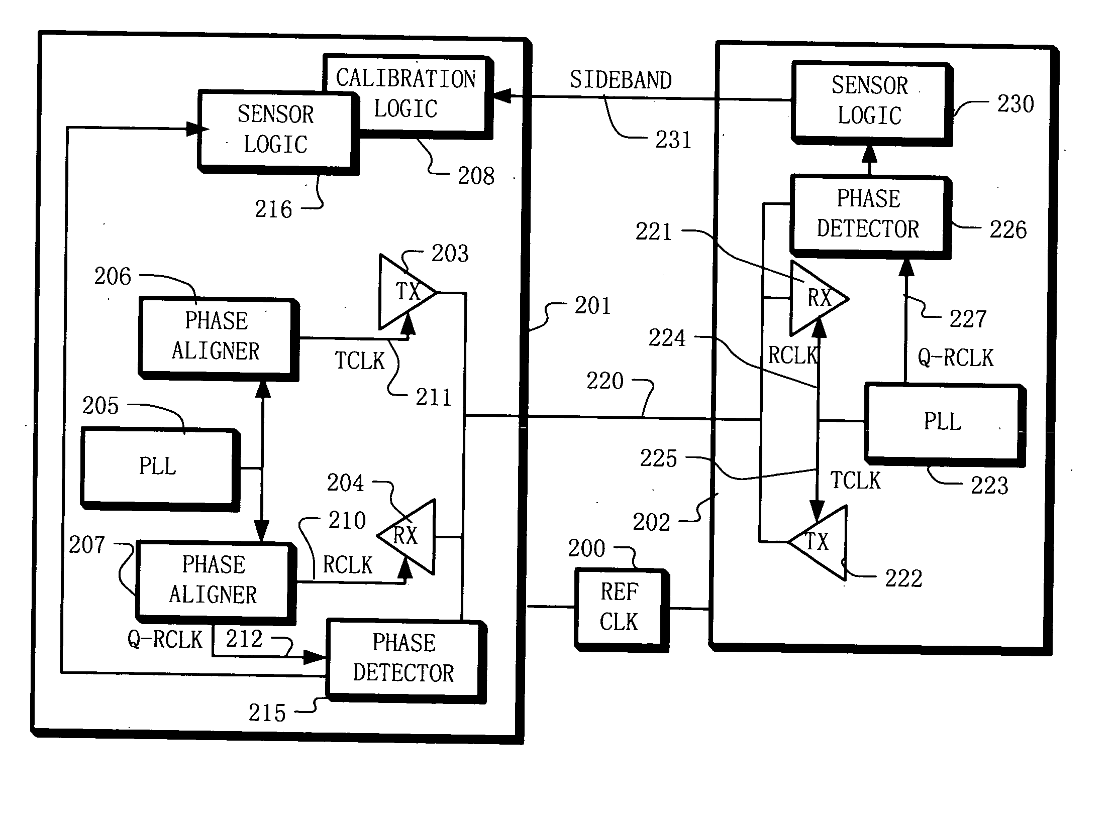
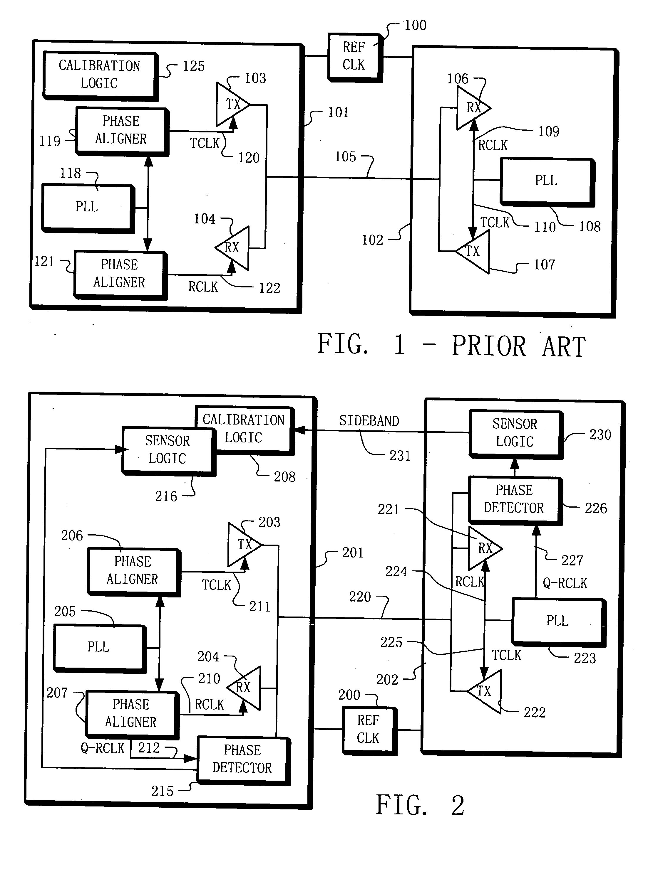
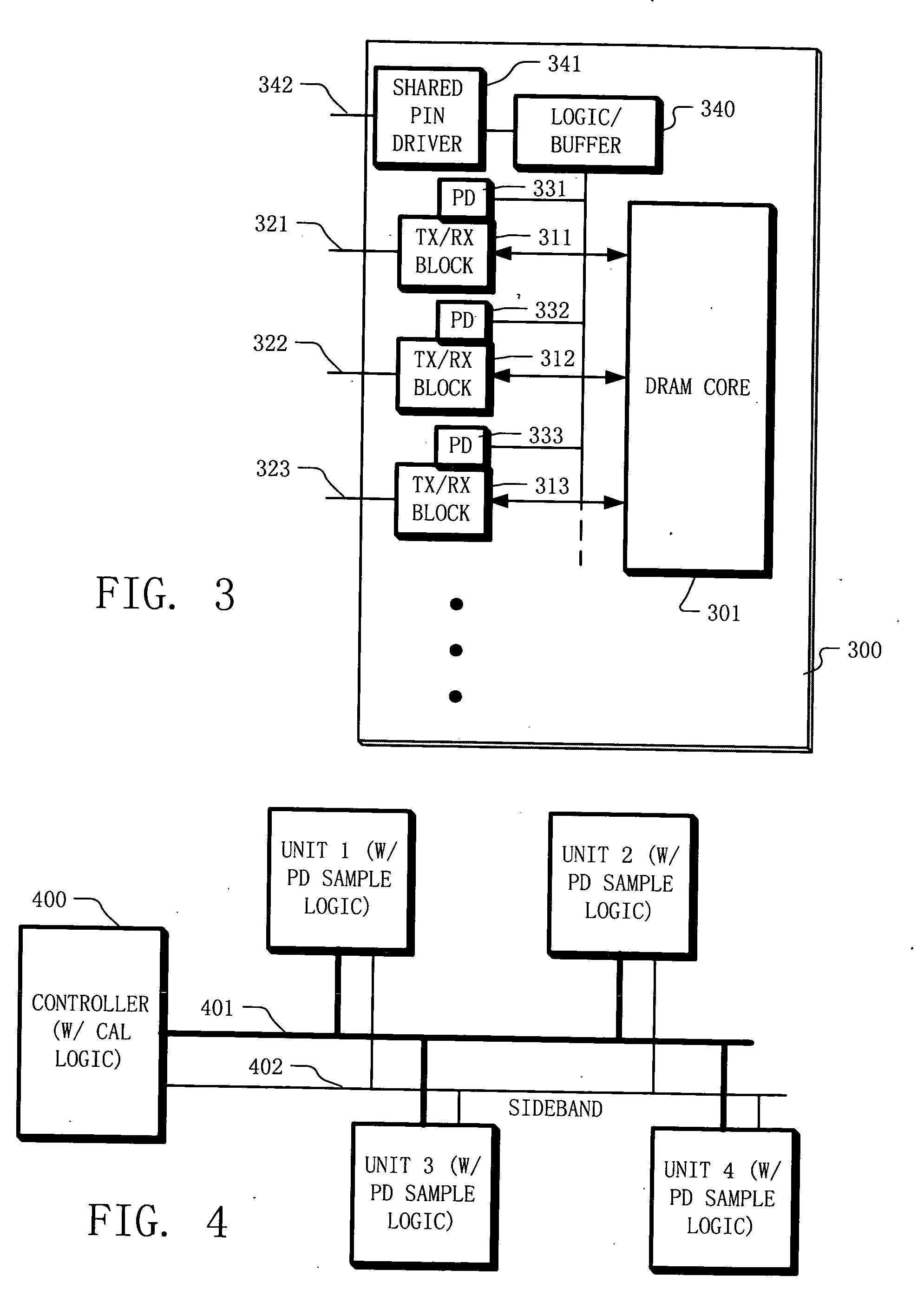
[0039] Example embodiments of the present disclosure include apparatus and methods for calibrating communication elements coupled using a communication channel. For example, the communication elements may include a first component and a second component. The first component having a transmitter with an adjustable parameter and the second component having a receiver. The method includes transmitting a data signal from the first component to the second component on the communication channel, and sensing a characteristic of the data signal on the second component. In some example embodiments, the step of sensing a characteristic of the data signal is performed in parallel with sensing the data values carried by the data signal. Information about the sensed characteristic is fed back to the first component. This information may be fed back to the first component using an auxiliary channel or a variety of other communication methods. For example, a dedicated signal line (e.g. a “sideband...


PUM


Abstract

A method for calibrating a communication channel coupling first and second components includes transmitting a data signal from the first component to the second component on the communication channel, and sensing a characteristic, such as phase, of the data signal on the second component. Information about the sensed characteristic is fed back to the first component using an auxiliary channel. An adjustable parameter, such as phase, for the transmitter is adjusted on the first component in response to the information. Also, a characteristic of a data signal received from the transmitter on the second component is sensed and used to adjust an adjustable parameter for the receiver on the first component.

Description

BACKGROUND OF THE INVENTION [0001] 1. Field of the Invention [0002] The present invention relates to calibration of communication channel parameters in systems, including mesochronous systems, in which two (or more) components communicate via an interconnection link; and to calibration to account for drift of conditions related to such parameters during operation of the communication channels. [0003] 2. Description of Related Art [0004] In high-speed communication channels, which are operated in a mesochronous manner, typically a reference clock provides frequency and phase information to the two or more components on the link. A transmitter on one component and a receiver on another component each connect to the link. The transmitter and receiver operate in different clock domains, which have an arbitrary (but fixed) phase relationship to the reference clock. The phase relationship between transmitter and receiver is chosen so that the propagation delay seen by a signal wavefront p...

Claims


Application Information

Patent Timeline
IPC IPC(8): H04L12/56
CPCH04L5/1438H04L2025/03802H04L25/03343H04B17/11
Inventor KIM, JUNRICHARDSON, WAYNE S.CHIU, GLENN
Owner RAMBUS INC
Learn More