
Enhanced LNG tanker offloading in shallow waters

a technology of lng tanker and shallow water, which is applied in the direction of container discharging from pressure vessels, special dispensing means, coastline protection, etc., can solve the problems of sudden increase in chain tension, increased cost of platform that is large enough to carry such gas heating and pumping systems, and increased cos

Active Publication Date: 2005-12-15
SINGLE BUOY MOORINGS INC
View PDF7 Cites 12 Cited by
  • Summary
  • Abstract
  • Description
  • Claims
  • Application Information

AI Technical Summary

Benefits of technology

The invention provides a system for mooring a tanker carrying cold hydrocarbons in shallow depths and regasing them for use in an onshore installation. The system includes a floating structure such as a barge and a simple tower, or a fixed structure in the form of a breakwater. The tanker is attached to the barge so they weathervane together. The system also includes a regas unit, a pressurizing unit, and crew quarters, all located on the barge. The breakwater has a length at least 60% of the tanker length and a width no more than one-fourth of its length. The regas and pressurizing units can be electrically energized, and electric power is carried between an onshore electric power station and the structure on which the regas and pressurizing units lie. The invention provides a cost-effective solution for mooring and regasing tankers in shallow depths.

Problems solved by technology

A platform that is large enough to carry such gas heating and pumping systems can be expensive even in shallow waters.
However, in shallow depths (e.g. less than about 70 meters), drifting of the vessel tends to lift the entire length of chain off the sea floor.
This can result in a sudden increase in chain tension rather that a gradual increase that is required.

Method used


Image

  • Enhanced LNG tanker offloading in shallow waters
  • Enhanced LNG tanker offloading in shallow waters
  • Enhanced LNG tanker offloading in shallow waters

Examples


Embodiment Construction

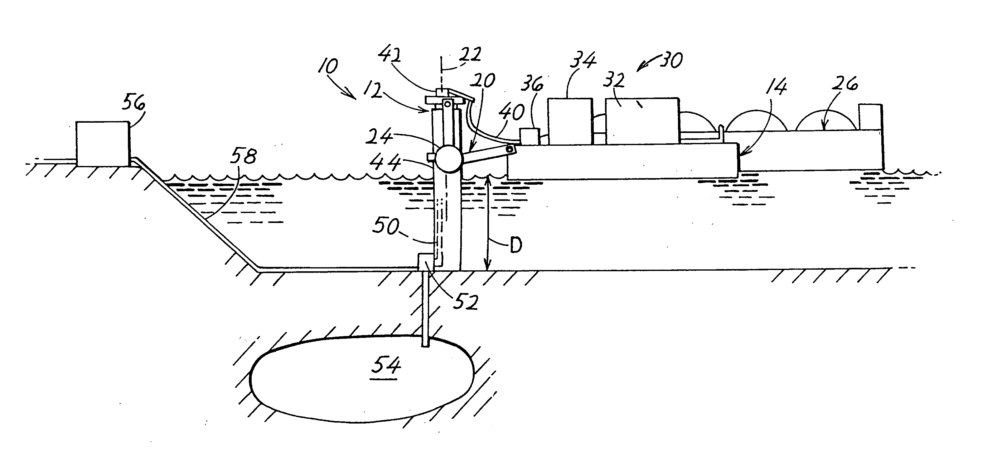
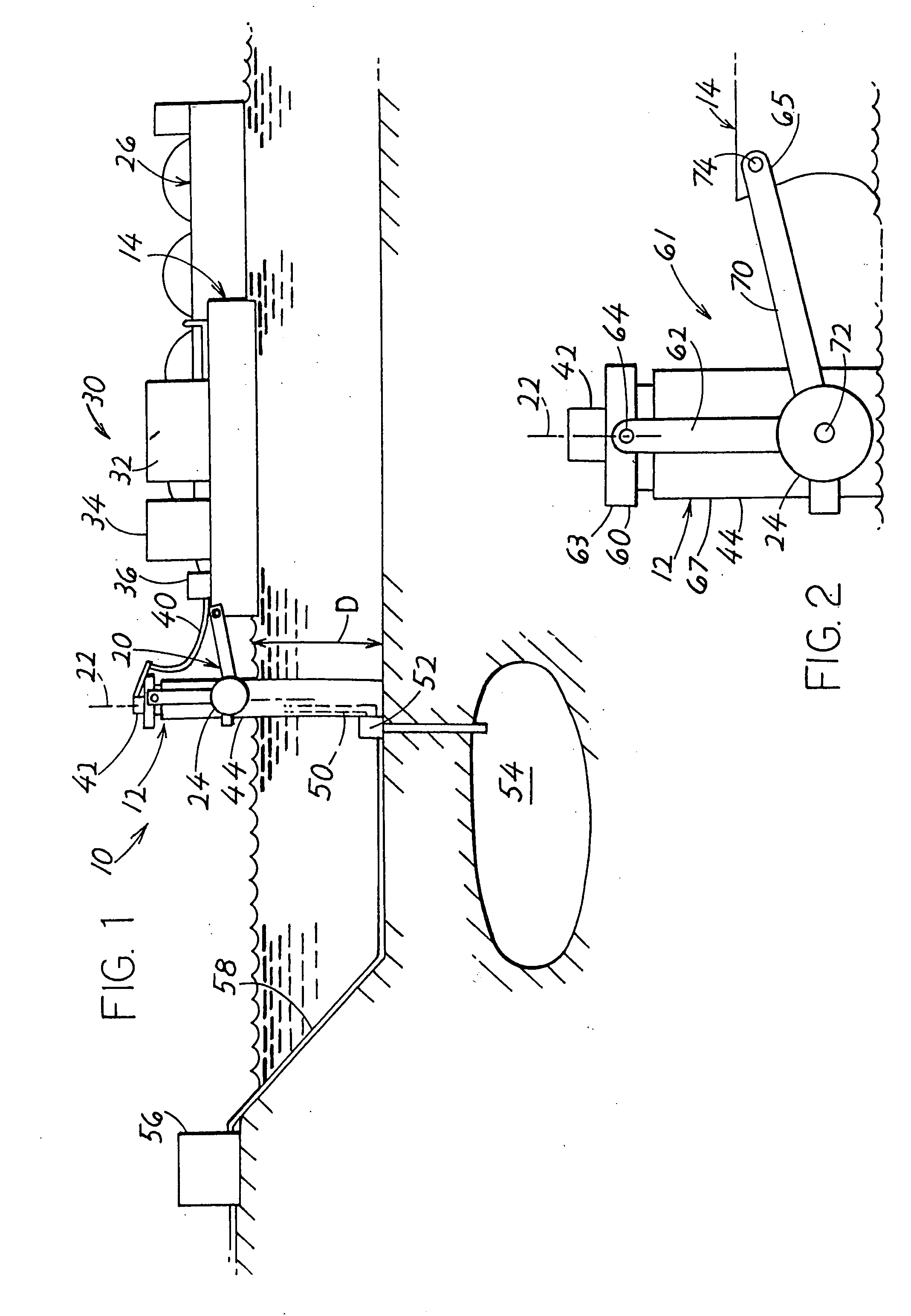
[0020]FIG. 1 illustrates an offloading / injection system 10 for shallow water, in which a moderate cost fixed tower 12 is used in conjunction with a floating and weathervaning structure in the form of a barge 14. A yoke 20 which can rotate around the tower axis 22, allows the floating and weathervaning barge to drift a limited distance away from the tower and urges the barge back towards the tower, as with counterweights 24. Thus, the barge can weathervane, to head in different directions with changes in winds, waves and currents and can move slightly away and back towards the tower to minimize the forces resulting from large waves. A tanker 26 is moored directly to the barge and weathervanes with it.

[0021] The tanker carries cold hydrocarbons that are cooled well below 0° C., and which must be heated to at least 0° C. before they can be pressurized and flowed though a pipeline to shore. The most common type of such cold hydrocarbons is LNG (liquified natural gas) which has been coo...


PUM


Abstract

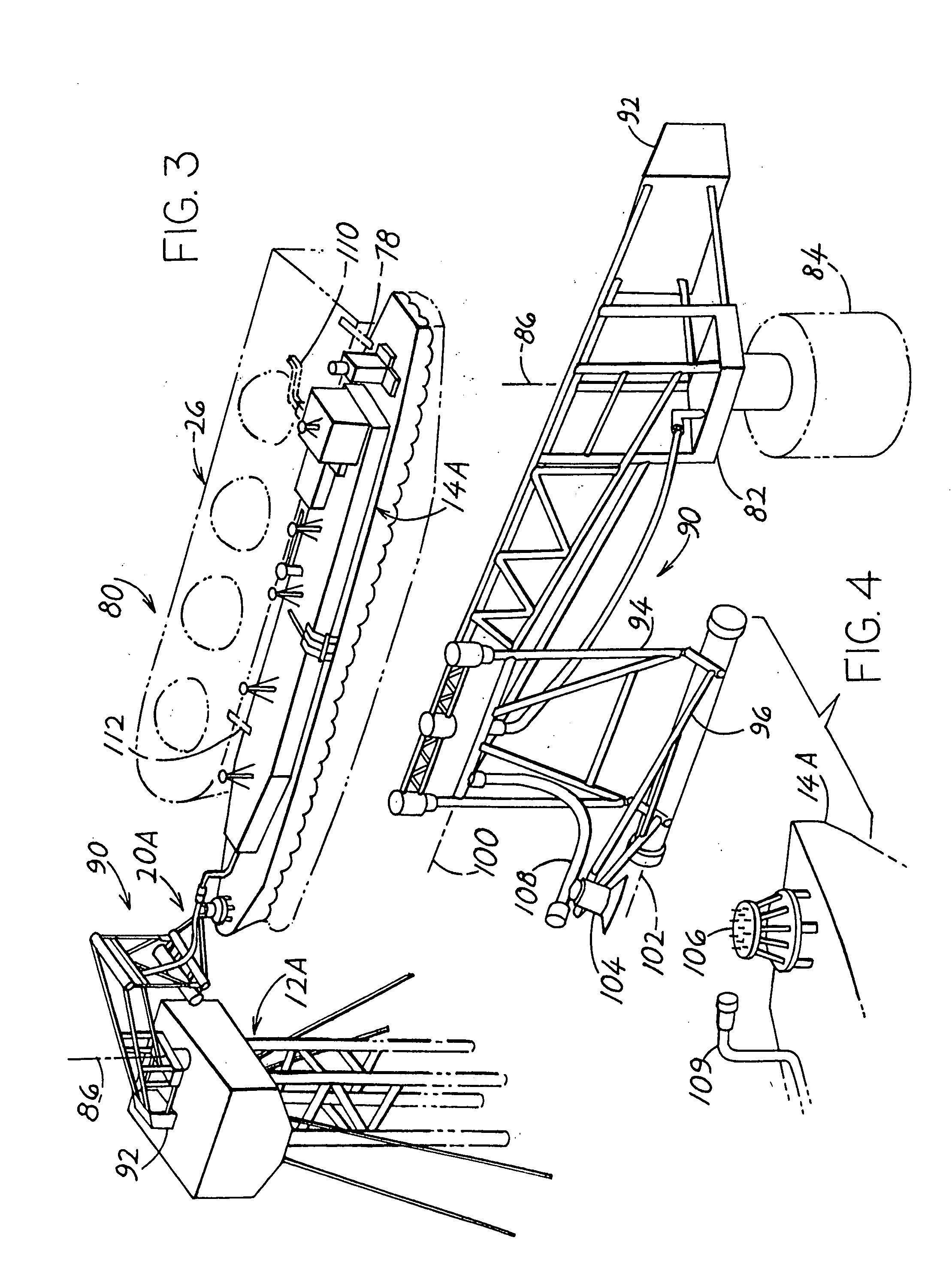
A system for offloading LNG (liquified natural gas) from a tanker (26) in shallow waters, for regasing, or heating the offloaded LNG to produce gaseous hydrocarbons, or gas, for pressurizing the gas, and for flowing the gas to an onshore station (56), includes a structure that is fixed to the sea floor and projects above the sea surface and aids in mooring the tanker. In one system, the structure that is fixed to the sea floor is a largely cylindrical tower (12) with a mooring yoke (20) rotatably mounted on its upper end. A floating structure (14) such as a barge that weathervanes, has a bow end pivotally connected to a distal end of the yoke, so the barge is held close to the tower but can drift around the tower with changing winds, waves and currents. The tanker is moored to the tower so the barge and tanker form a combination that weathervanes as a combination. Regas and pressurizing equipment (32, 34) for heating and pressuring the LNG, and any crew quarters (36), are all located on the barge, so a low cost tower can be used. In another system, the structure is a breakwater (180).

Description

CROSS-REFERENCE [0001] Applicant claims priority from U.S. provisional applications Ser. No. 60 / 515,767 filed Oct. 30, 2003, Ser. No. 60 / 550,133 filed Mar. 4, 2004, and Ser. No. 60 / 559,989 filed Apr. 5, 2004.BACKGROUND OF THE INVENTION [0002] Hydrocarbons that are gaseous at room temperature such as 20° C., are often transported by tanker as LNG (liquified natural gas) at −160° C. and atmospheric pressure. Other cold forms during transport are hydrates (gas entrapped in ice) and cooled CNG (compressed natural gas that has been cooled well below 0° C. to reduce the pressure required to keep it liquid). At the tanker's destination, the LNG (or other cold gas) may be offloaded, heated and pressurized, and carried by pipeline to an onshore station for distribution (or possibly for use as by a power plant at the onshore station). [0003] Proposed prior art offloading and regas / injection systems (for heating and pressuring LNG) include a fixed platform extending up from the sea floor to a ...

Claims


Application Information

Patent Timeline
Patent Type & Authority Applications(United States)
IPC IPC(8): B67D9/00E02B1/00E02B17/00E02B17/08E02D23/00E02D23/02F17C
CPCB63B21/507F17C2270/0163F17C7/04F17C2221/033F17C2223/0161F17C2223/033F17C2225/0123F17C2225/035F17C2227/0135F17C2227/0302F17C2227/0393F17C2265/05F17C2265/07F17C2270/0105F17C2270/0113F17C2270/0155F17C2270/016B63B27/24
Inventor WILLE, HEINPOLLACK, JACK
Owner SINGLE BUOY MOORINGS INC
Learn More