Solid polymer type fuel cell, metal separator for fuel cell, and kit for fuel cell

Inactive Publication Date: 2005-12-15
HITACHI LTD
View PDF1 Cites 21 Cited by
  • Summary
  • Abstract
  • Description
  • Claims
  • Application Information

AI Technical Summary

Benefits of technology

[0015] According to the present invention, gas distribution channel groups in the cell can be divided into a plurality by making the number of supply manifolds and/or discharge manifolds to be p

Problems solved by technology

In the above described technology, however, since gas flowing from the gas channel portion concentrates at the turn-around portions where the gas is made to turn, this results in the problem that the gas pressure loss is large.
In a fuel cell power generation system, if the gas pressure loss value of the fuel cell is large, a high blow pressure air blower has to be employed, thus increasing the ancillary machinery losses.
As a result, efficiency as a power generation system decreases.
While it is possible to increase the cross-sectional area of the gas channels which form the separator in o

Method used


Image

  • Solid polymer type fuel cell, metal separator for fuel cell, and kit for fuel cell
  • Solid polymer type fuel cell, metal separator for fuel cell, and kit for fuel cell
  • Solid polymer type fuel cell, metal separator for fuel cell, and kit for fuel cell

Examples


example 1

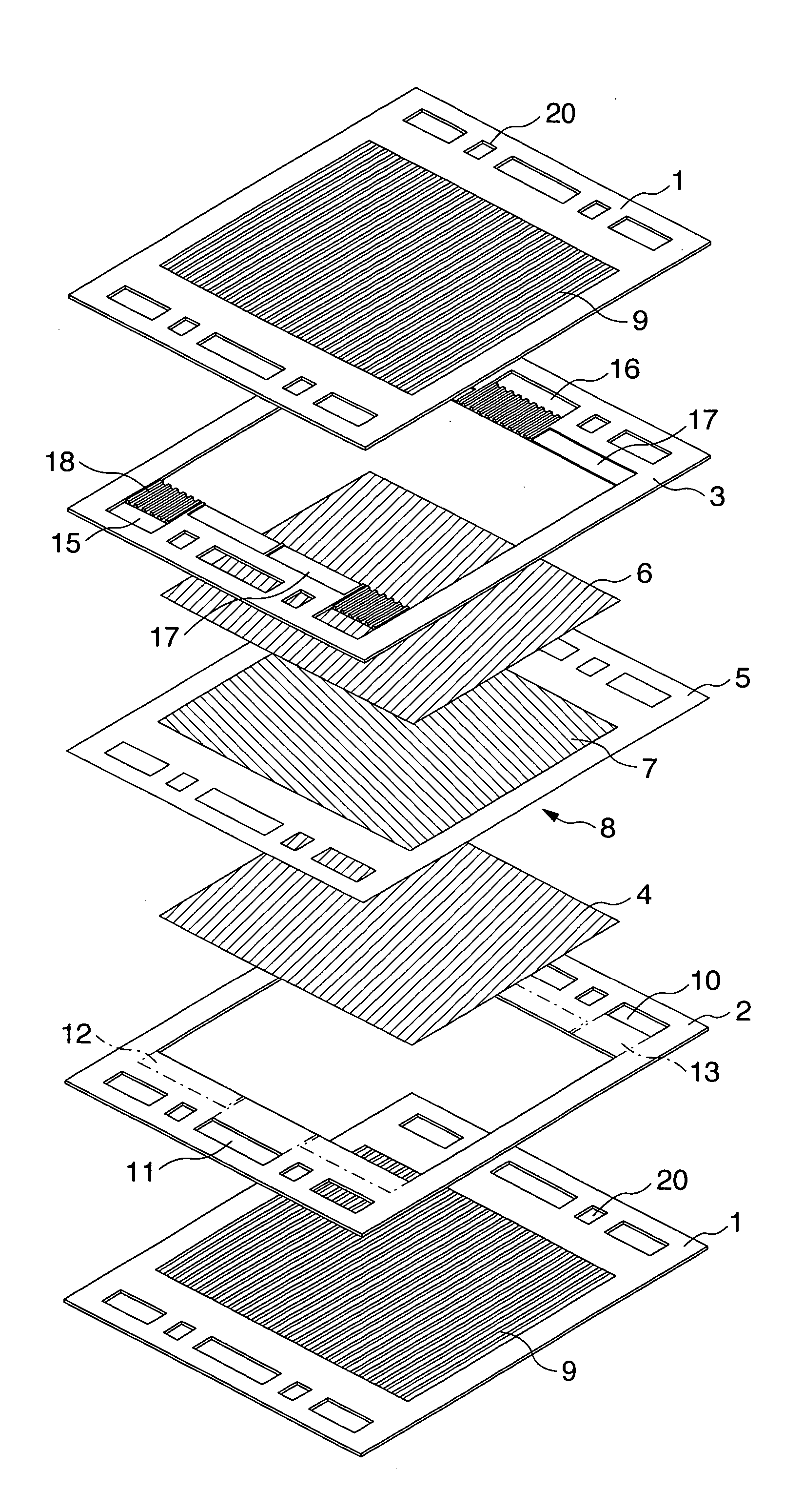
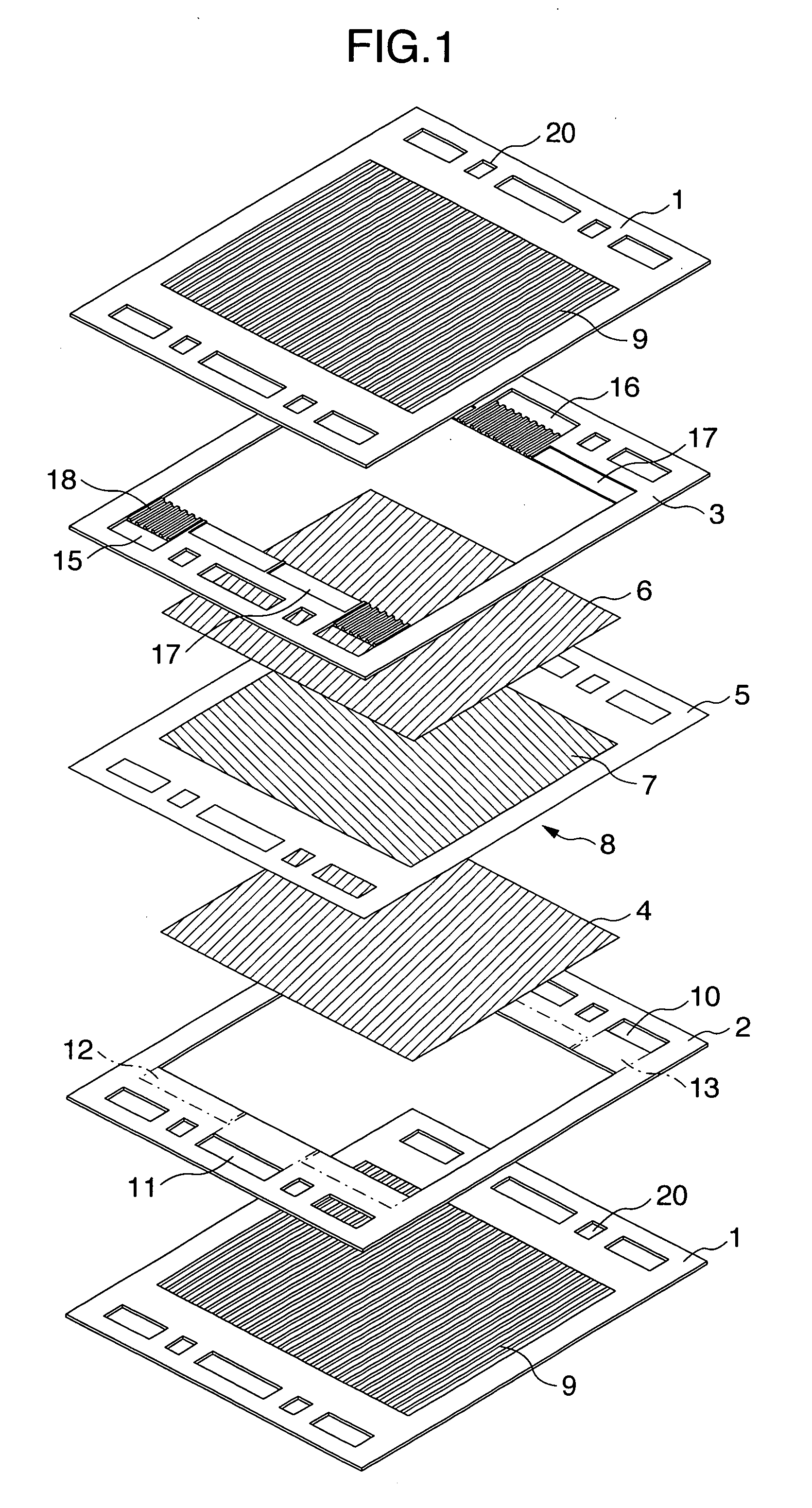
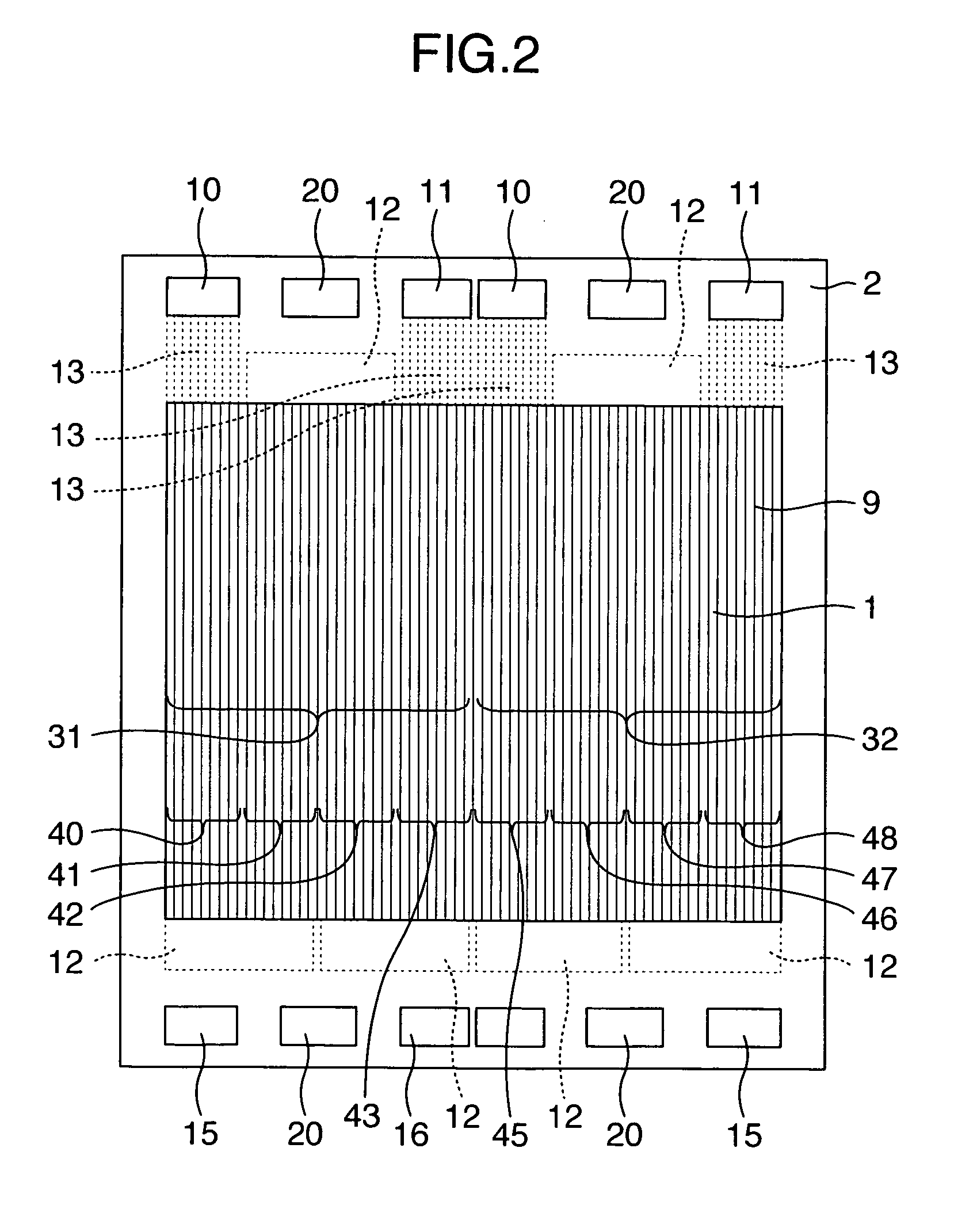
[0079] A 0.15 mm-thick stainless steel sheet having press-molded thereon 31 linear ridge / groove-shaped gas channels which had a gas channel pitch of 3 mm and an overhang of 0.3 mm was made to serve as a metal gas channel plate 1. On a 0.5 mm-thick sheet of PPS (polyphenylenesulfide) in which portions corresponding to the linear gas channels were in a hollowed out frame-shape, a cathode-side frame 2 was formed comprising a cathode gas supply manifold aperture 10, a cathode gas discharge manifold aperture 11, an anode gas supply manifold aperture 15, an anode gas discharge manifold aperture 16, a cathode turn-around portion 12, and three each of gas distribution channels A31 and distribution channels B32 for a total of 6 channels. The metal gas channel plate 1 and the frame 2 were adhered together using a liquid-state gasket so that there were no gaps therebetween, to thereby fabricate a cathode separator.

[0080] An external view of the cathode separator is illustrated in FIG. 2. In t...

example 2

[0086] A cathode-side frame 2 was formed comprising a cathode gas supply manifold aperture 10, a cathode gas discharge manifold aperture 11, an anode gas supply manifold aperture 15, an anode gas discharge manifold aperture 16, a cathode turn-around portion 12, and two each of gas distribution channels A31 and distribution channels B32 for a total of 4 channels. A metal gas channel plate 1 having linear ridge / groove-shaped gas channels 9 and the frame 2 were adhered together using a liquid-state gasket so that there were no gaps therebetween, to thereby fabricate a cathode separator. An external view of the cathode separator is illustrated in FIG. 3.

[0087] In this cathode separator, there are two gas distribution channels, gas distribution channel A31 and distribution channel B32, formed by the linear ridge / groove-shaped gas channels through which gas flows in the supply manifold, the discharge manifold and therebetween. Since each of the distribution channels 31 and 32 has 2 turn-...

example 3

[0088] A cathode-side frame 2 was formed comprising a cathode gas supply manifold aperture 10, a cathode gas discharge manifold aperture 11, an anode gas supply manifold aperture 15, an anode gas discharge manifold aperture 16, a cathode turn-around portion 12, and two each of gas distribution channels A31 and distribution channels B32 for a total of 4 channels. A metal gas channel plate 1 having linear ridge / groove-shaped gas channels 9 and the frame 2 were adhered together using a liquid-state gasket so that there were no gaps therebetween, to thereby fabricate a cathode separator. An external view of the cathode separator is illustrated in FIG. 4.

[0089] In this cathode separator, there are two gas distribution channels, gas distribution channel A31 and distribution channel B32, formed by the linear ridge / groove-shaped gas channels through which gas flows in the supply manifold, the discharge manifold and therebetween. Since each of the distribution channels 31 and 32 has 2 turn-...


PUM


Abstract

The present invention provides a fuel cell employing a metal separator in which low gas pressure loss, high hydrogen utilization factor operation and long term power generation are possible. The fuel cell according to the present invention is constituted by laminating a plurality of units, the units combining a metal gas channel plate having on both faces a frame portion and a plurality of gas channel sets formed inside the frame portion, a frame having a supply manifold for supplying reaction gas to an end turn-around portion of the gas channels closely attached to the frame portion of the above described metal gas channel plate and a discharge manifold for discharging reaction gas, a reaction gas diffusion layer in contact with the above described frame, an electrolyte membrane which is in contact with the above described diffusion layer and in which one side is in contact with an anode and another side in contact with a cathode, a reaction gas diffusion layer in contact with the above described anode or the above described cathode, the above described metal gas channel plate and the above described frame, wherein a plurality of supply manifolds and/or discharge manifolds are provided per each frame.

Description

INCORPORATION BY REFERENCE [0001] The present application claims priority from Japanese application JP 2004-175202 fled on Jun. 14, 2004, the content of which is hereby incorporated by reference into this application. BACKGROUND OF THE INVENTION [0002] The present invention relates to a polymer electrolyte fuel cell capable of extracting energy from a fuel and an oxidant by means of an electrochemical reaction, a metallic separator for a fuel cell, and a kit for a fuel cell. [0003] Polymer electrolyte fuel cells which use a proton-conducting polymer film as an electrolyte are a power generating system that is currently being researched. However, one problem to be resolved for practical use is high material costs. One of the high-cost materials which constitute a fuel cell is a separator. A separator segregates two reaction gases so that they do not mix, and is a term for an electron-conducting plate that is provided with gas channel grooves. When a fuel cell is generating power, the...

Claims


Application Information

Patent Timeline
IPC IPC(8): H01M8/24H01M4/94H01M8/02H01M8/04H01M8/10
CPCH01M8/0258H01M8/0273Y02E60/50H01M8/242H01M8/04089H01M8/026H01M8/0267H01M8/2483H01M8/241
Inventor YAMAGA, KENJIYAMAUCHI, HIROSHITAKAHASHI, KOU
Owner HITACHI LTD
Why Eureka
Try Eureka