

Apparatus with microtiter plate format for multiplexed arraying
a technology of multiplexed arraying and microtiter plate, which is applied in the field of apparatus with microtiter plate format for multiplexed arraying, can solve the problems of inability to successfully interface conventional microtiter plate designs with conventional microtiter plate fabrication, and the inability to achieve contact pin or inkjet printing of microarrays, so as to improve the effect of multiplexed microarraying
Inactive Publication Date: 2005-12-15
HAINES DAN +3
View PDF10 Cites 20 Cited by
- Summary
- Abstract
- Description
- Claims
- Application Information
AI Technical Summary
Benefits of technology
The present invention is about an apparatus and kit for improved multiplexed microarraying using microtiter plates. It overcomes the limitations of conventional plastic and glass bottom microtiter plates. The invention includes a low self-fluorescent coated substrate with a pattern of wells and a flexible superstructure with matching through holes that can be adhesively attached to the substrate. The substrate can be a low self-fluorescent glass coated with a functional coating for bonding other biomolecules. The invention allows for more efficient and accurate multiple biomolecular assays.
Problems solved by technology
The emergence of multiplexed microarraying in the microtiter plate format has been inhibited from widespread acceptance due to technical limitations.
Conventional microarray fabrication has not been successfully interfaced with conventional microtiter plate designs, thus the bulk of multiplexed microarraying occurs on microscope sized coated substrates in various formats.
At present the primary limitations include difficulties associated with contact pin or inkjet printing of microarrays into conventional 2-13 mm recessed microtiter plate wells, and the inability to print the entire intra-well surface with microarray probes due to adhesive contamination.
Microtiter plates, used in many scientific disciplines for assaying, drug discovery, purification, combinatorial chemistry, etc., are generally not suitable for microarraying due to difficulty in applying the wide range of functional coatings used in microarraying to the polymeric microtiter plate.
Additionally, conventional microtiter plates suffer from issues of lack of optical transparency and flatness issues associated with the wells.
This leads to problems with fluorescence detection.
However, these still are not optimized for microarraying as the full well area cannot be used for printing probes as opposed to the comparable well area on a standard, coated glass substrate due to the well wall thickness and finite thickness of the pins used to deposit probes.
Due to the well height of the typical microtiter plate and the longer z-axis travel time for well-to-well probe deposition the printing of microarray probes is difficult and time consuming.
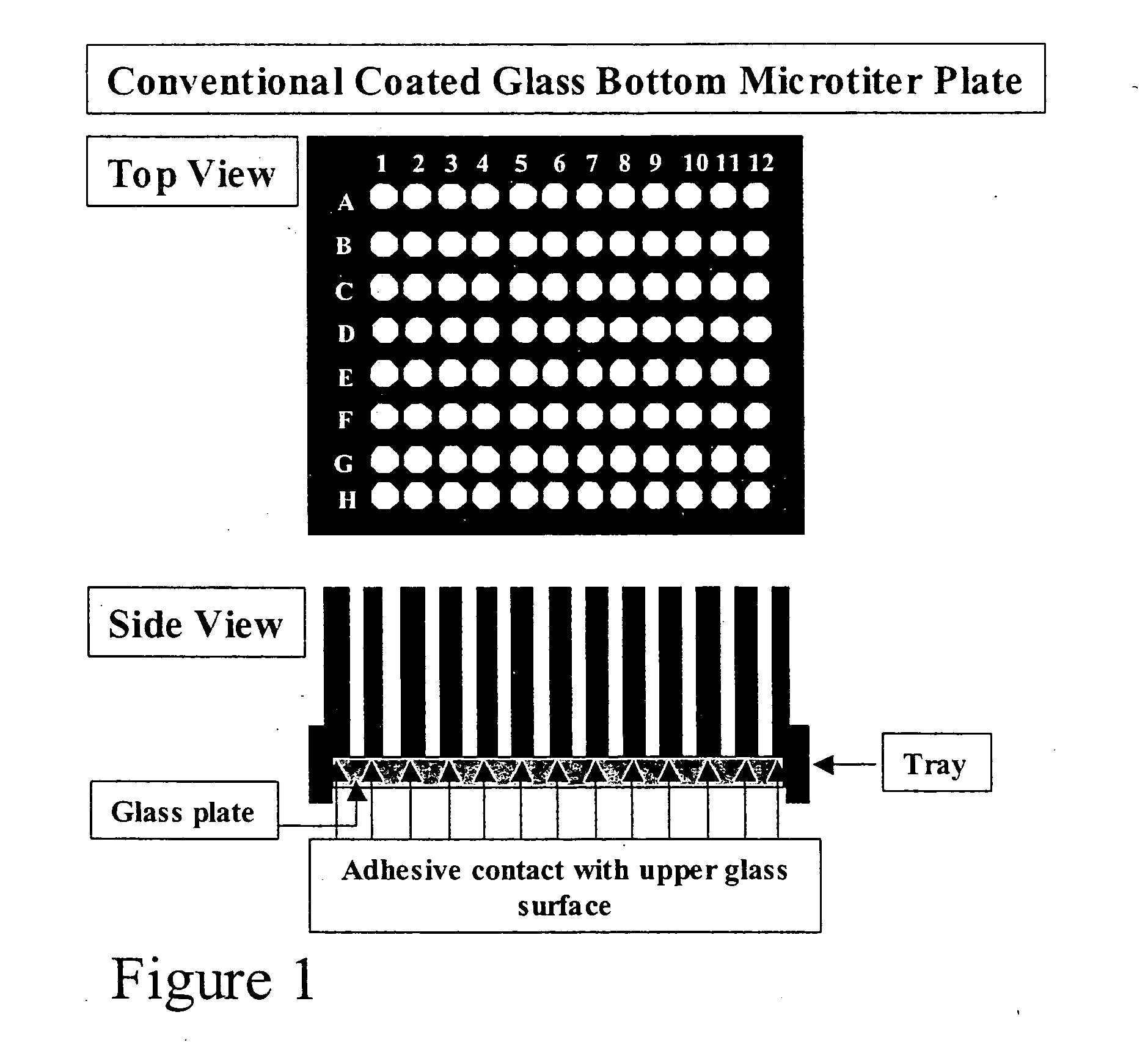
Such gluing often results in intra-well adhesive contamination, which can deleteriously affect microarray fabrication, and inevitably microarray performance. FIG. 1 shows the design for a conventional glass bottom microtiter plate.
Method used
View moreImage
Smart ImageViewing Examples

Examples
example 1
Reduction of Well Contamination
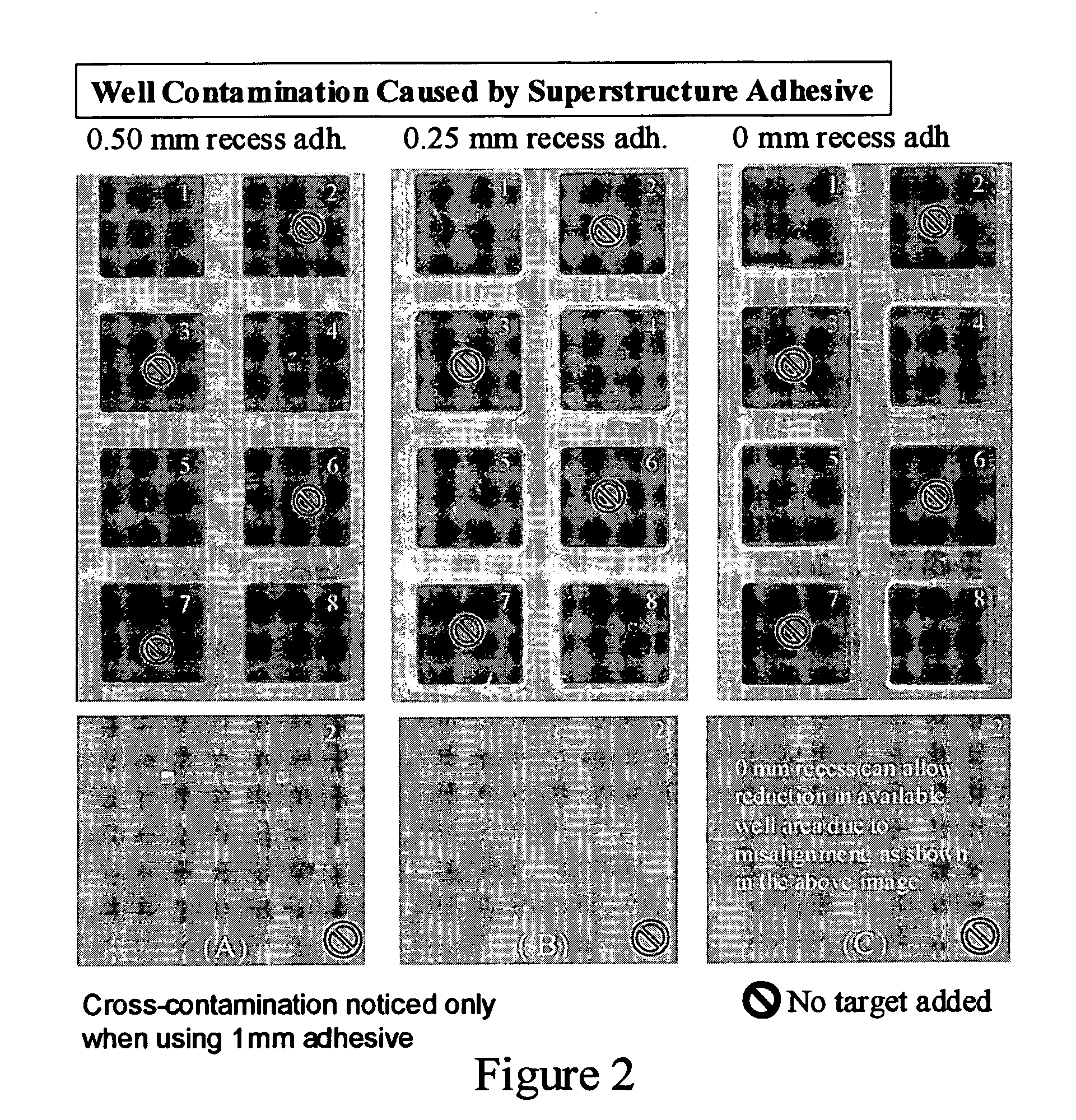
[0046]FIG. 2 depicts the elimination of well contamination by reducing the amount of the adhesive on the flexible superstructure around the wells on epoxy silanized patterned glass substrates. A complex hybridization experiment is conducted using a 10×10 array of 50 mer (rat) probes, and a mixture of CDNA Cy3 labeled kidney and Cy5 labeled liver targets are added to wells 1, 4, 5, 8. As demonstrated, full adhesive around the wells (FIG. 2c) leads to reduction in printable well area and well contamination from the adhesive, while reducing the adhesive too much around the wells (FIG. 2a) leads to intra-well cross contamination.
Login to View More PUM
| Property | Measurement | Unit |
|---|---|---|
| thickness | aaaaa | aaaaa |
| thickness | aaaaa | aaaaa |
| thickness | aaaaa | aaaaa |
Abstract
The present invention relates generally to an apparatus and kit in the microtiter plate format for improved multiplexed microarraying. The apparatus overcomes current limitations with conventional polymeric and glass bottom microtiter plates. The invention also relates to an apparatus for conducting multiple biomolecular assays comprising a low self-fluorescent coated substrate having an upper and lower surface. The substrate upper surface has a pattern comprising a plurality of wells. A flexible superstructure having a plurality of through holes (i.e. openings) in a pattern that is similar to and aligns with the wells on the substrate is removably adherable to the upper surface of the substrate. Preferably, the superstructure is adhesively attachable to the substrate. A tray supports the substrate and the superstructure and acts as an alignment jig. In a preferred embodiment the substrate is low self-fluorescent glass and coated on the upper surface with a functional coating to which other biomolecules can bond.
Description
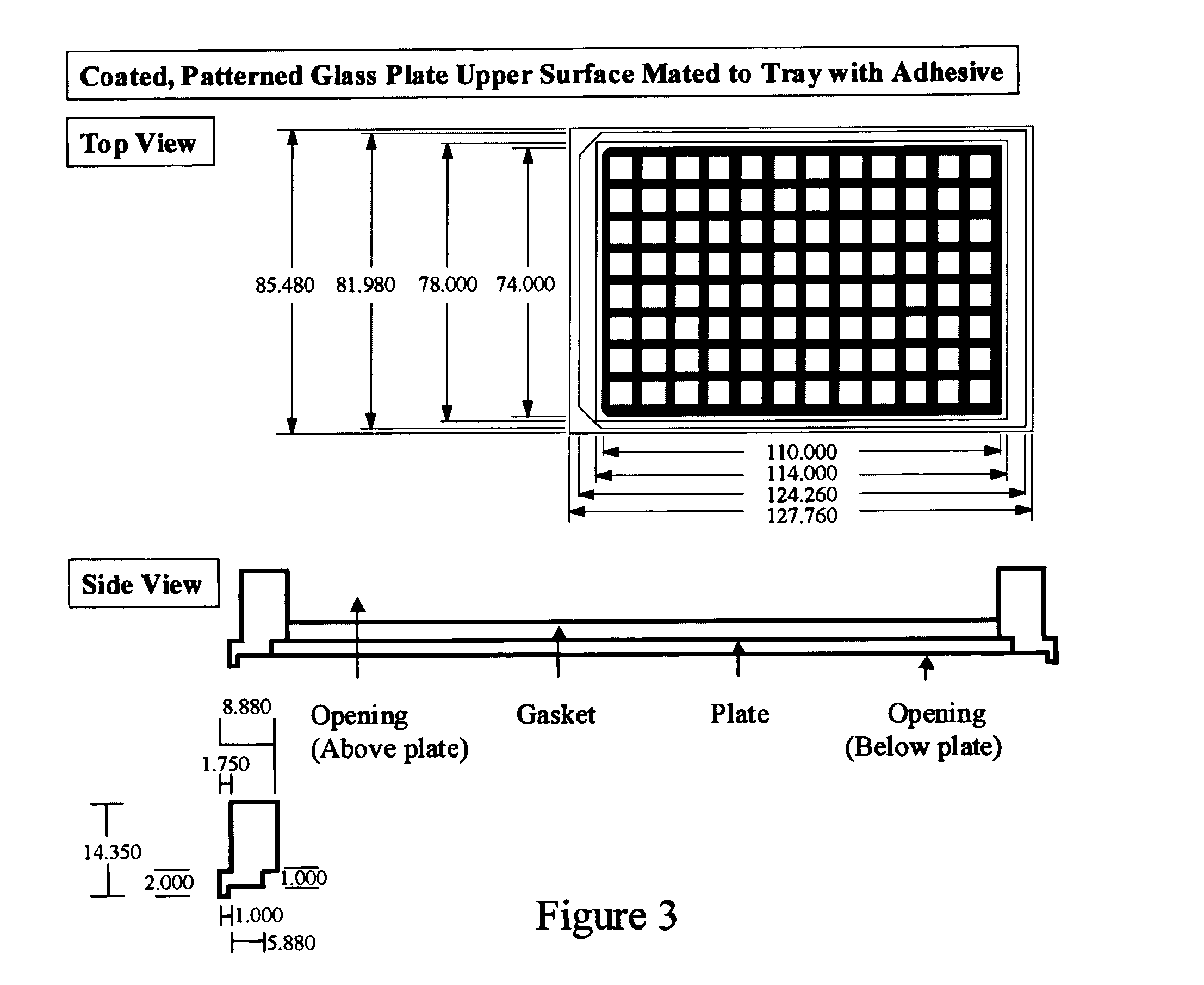
[0001] The present invention relates generally to an apparatus in the microtiter plate format for improved multiplexed microarraying. The apparatus overcomes current limitations with conventional polymeric and glass bottom microtiter plates. The invention also relates to an apparatus for conducting multiple biomolecular assays comprising a low self-fluorescent coated substrate having an upper and lower surface. The substrate upper surface has a plurality of wells and a flexible superstructure having a plurality of through holes (i.e. openings) in a pattern that is similar to and aligns with the wells on the substrate and is removably adherable to the upper surface of the substrate. Preferably, the superstructure is adhesively attachable to the substrate. More preferably the adhesive is strategically recessed on the underside of the flexible superstructure from about 0.15 mm to 0.50 mm from all well openings. Most preferably, a tray supports the substrate and the superstructure. In a...
Claims
Login to View More Application Information
Patent Timeline
 Patent Type & AuthorityApplications(United States)
IPC IPC(8): B01J19/00B01L3/00C12M1/34C12Q1/68
CPCB01J19/0046B01L2300/0851B01J2219/00317B01J2219/00364B01J2219/00378B01J2219/00387B01J2219/00497B01J2219/00527B01J2219/00533B01J2219/00576B01J2219/00585B01J2219/00596B01J2219/00605B01J2219/00612B01J2219/00619B01J2219/00621B01J2219/00637B01J2219/00659B01J2219/00662B01J2219/00677B01J2219/00691B01J2219/00722B01J2219/00725B01J2219/00731B01J2219/00734B01L3/5085B01L2200/0689B01L2200/12B01L2300/0636B01L2300/0829B01J2219/00315
InventorHAINES, DANCONZONE, SAMUEL D.REDKAR, RAJENDRA J.GRANKO, JOSEPH J.
OwnerHAINES DAN