Minimally invasive surgical spinal exposure system

Active Publication Date: 2005-12-15
ZIMMER BIOMET SPINE INC
View PDF38 Cites 135 Cited by
  • Summary
  • Abstract
  • Description
  • Claims
  • Application Information

AI Technical Summary

Benefits of technology

[0009] The minimally invasive surgical fixation system of the invention will eliminate many of the previously discussed limiting factors of the presently existing systems. A surgeon who prefers direct visualization by looking down the surgical portal, or the surgeon who prefers indirect visualization with a scope can use this new system. The new system concept of the invention will offer superior lighting and visualization when compared to the systems presently on the

Problems solved by technology

As these techniques have been developed, workers and surgeons have been faced with the problem of working in small places not visible by direct line of sight.
Various tools have been designed to deal with this problem although none has been entirely satisfactory.
Even with the advent of minimally invasive surgical techniques, many surgical procedures still require an exposed surgical field for the surgeon to successfully perform.
Many traditional surgical procedures for correction of disc space pathologies can cause significant trauma to the intervening tissues.
These open procedures often require a long incision, extensive muscle stripping, prolonged retraction of tissues, denervation and devascularization of tissue.
Most of these surgeries require significant pos

Method used


Image

  • Minimally invasive surgical spinal exposure system
  • Minimally invasive surgical spinal exposure system
  • Minimally invasive surgical spinal exposure system

Examples


Example

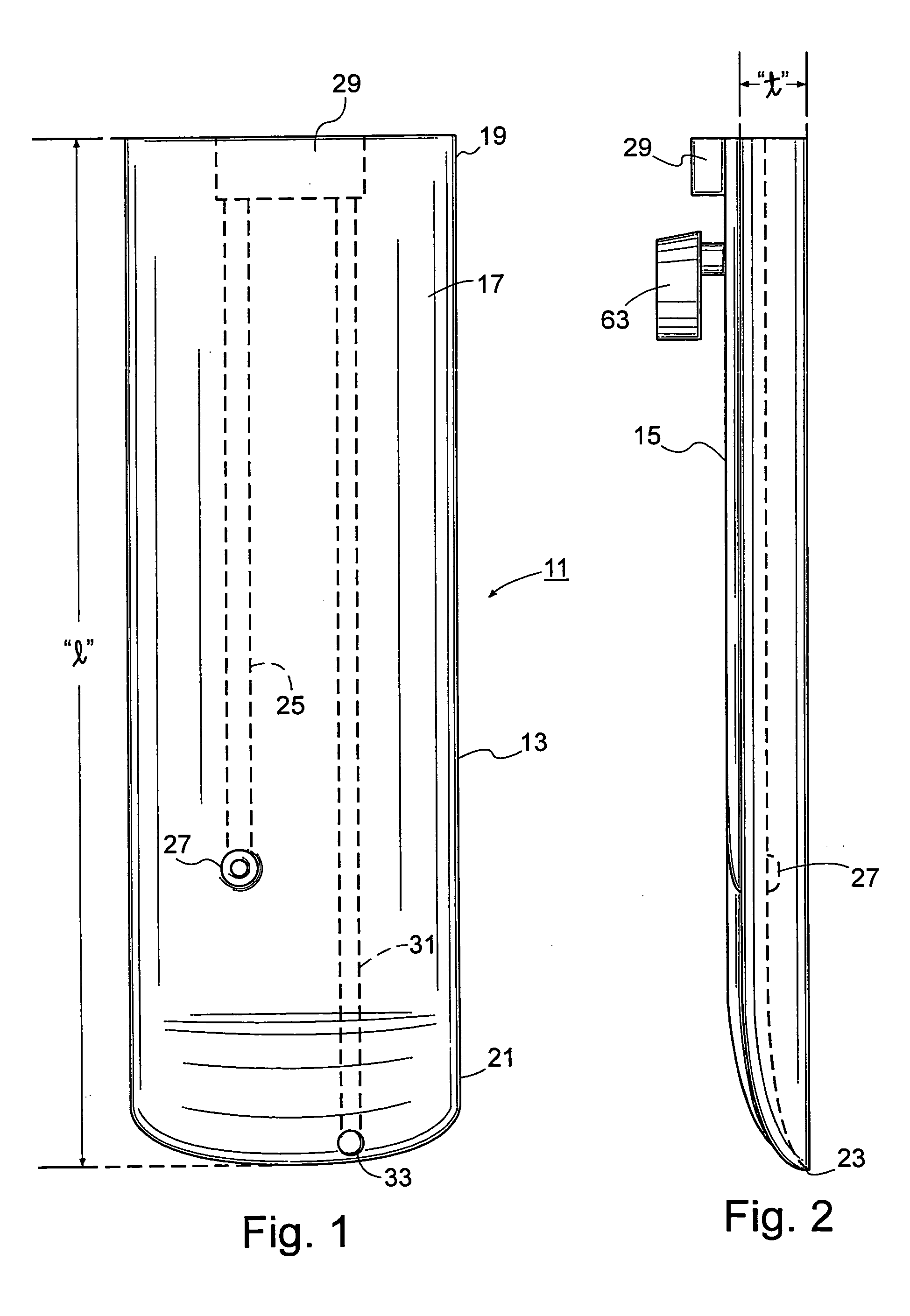
[0026] Turning to FIG. 1, there is shown a retractor blade 11 of the type used in the practice of the present invention. The retractor blade 11 has a substantially elongate, planar body portion 13 having a length “1” and having a thickness (“t” in FIG. 2). The body portion 13 is also defined by an outer planar surface 15 and an inner planar surface 17. As best seen in FIG. 2, the body portion is generally uniform in thickness along the width thereof but tapers from an upper extent 19 as it approaches a lower extent 21, terminating in a tip region 23.

[0027] The elongate body portion 13 of the retractor blade has incorporated therein at least one visualization channel 25 which, in the embodiment of FIG. 1, runs from the upper extent 19 down about ⅘ of the length of the blade. The visualization channel 25 is used to house a light source which is integral with the blade itself. For example, the light source could be a light bulb 27 which is connected by electrical wires running up the ...


PUM


Abstract

A minimally invasive retractor system is shown which has a support frame having two opposing pairs of horizontally oriented sides. The sides of the frame can be adjusted to vary an interior space of the frame. Four retractor blades are mounted on the frame for engaging tissue within a surgical site. Each retractor blade has an elongate body portion with a length which is oriented perpendicularly to the frame in use. One of the retractor blades can be equipped with a light source and a suction source which are integral to the blade. The blade also has an integral power source for powering the light source. The blade can also house a tissue retractor such as a dural retractor for retracting the dural sack of a patient during spinal surgery.

Description

BACKGROUND OF THE INVENTION [0001] A. Field of the Invention [0002] The present invention relates generally to the field of minimally invasive surgical instruments, and more particularly, to a visual blade retractor system which will allow greater access and visual exposure in the surgical area, along with improved instrument control, orientation and versatility. [0003] B. Description of the Prior Art [0004] Minimally invasive surgical techniques have become increasingly popular due to the rapid healing and greater efficiency provided by such techniques. As these techniques have been developed, workers and surgeons have been faced with the problem of working in small places not visible by direct line of sight. Various tools have been designed to deal with this problem although none has been entirely satisfactory. [0005] The standard surgical approach has been to make a large enough opening in an anatomically suitable location (which will heal without functional impairment) to establ...

Claims


Application Information

Patent Timeline
IPC IPC(8): A61B1/32A61B17/02A61B19/00
CPCA61B17/0206A61B19/5212A61B19/5202A61B17/0293A61B90/30A61B90/361
Inventor MYLES, ROBERT T.
Owner ZIMMER BIOMET SPINE INC
Why Eureka
Try Eureka