Miter gauge, jig and fixture improvements

a technology of miter gauges and jigs, which is applied in the field of shopmade jigs and fixtures, can solve the problems of inability to adjust the fine angle of the miter gauge until now, and achieve the effect of convenient use and more accurate cutting of better quality workpieces

Inactive Publication Date: 2005-12-22
ALLEN IP
View PDF11 Cites 20 Cited by
  • Summary
  • Abstract
  • Description
  • Claims
  • Application Information

AI Technical Summary

Benefits of technology

[0013] The invention provides improvements to a miter gauge and jig and fixture system that make them more accurate and easy to use to cut better quality workpieces.

Problems solved by technology

The machined numerals of the '966 patent, which are very expensive to manufacture because they are individually machined, are wide because of the cutter width and are hard to read.
No miter gauge manufactured until now has had adjustable fine angle tuning using ordinary shop tools.

Method used


Image

  • Miter gauge, jig and fixture improvements
  • Miter gauge, jig and fixture improvements
  • Miter gauge, jig and fixture improvements

Examples


Embodiment Construction

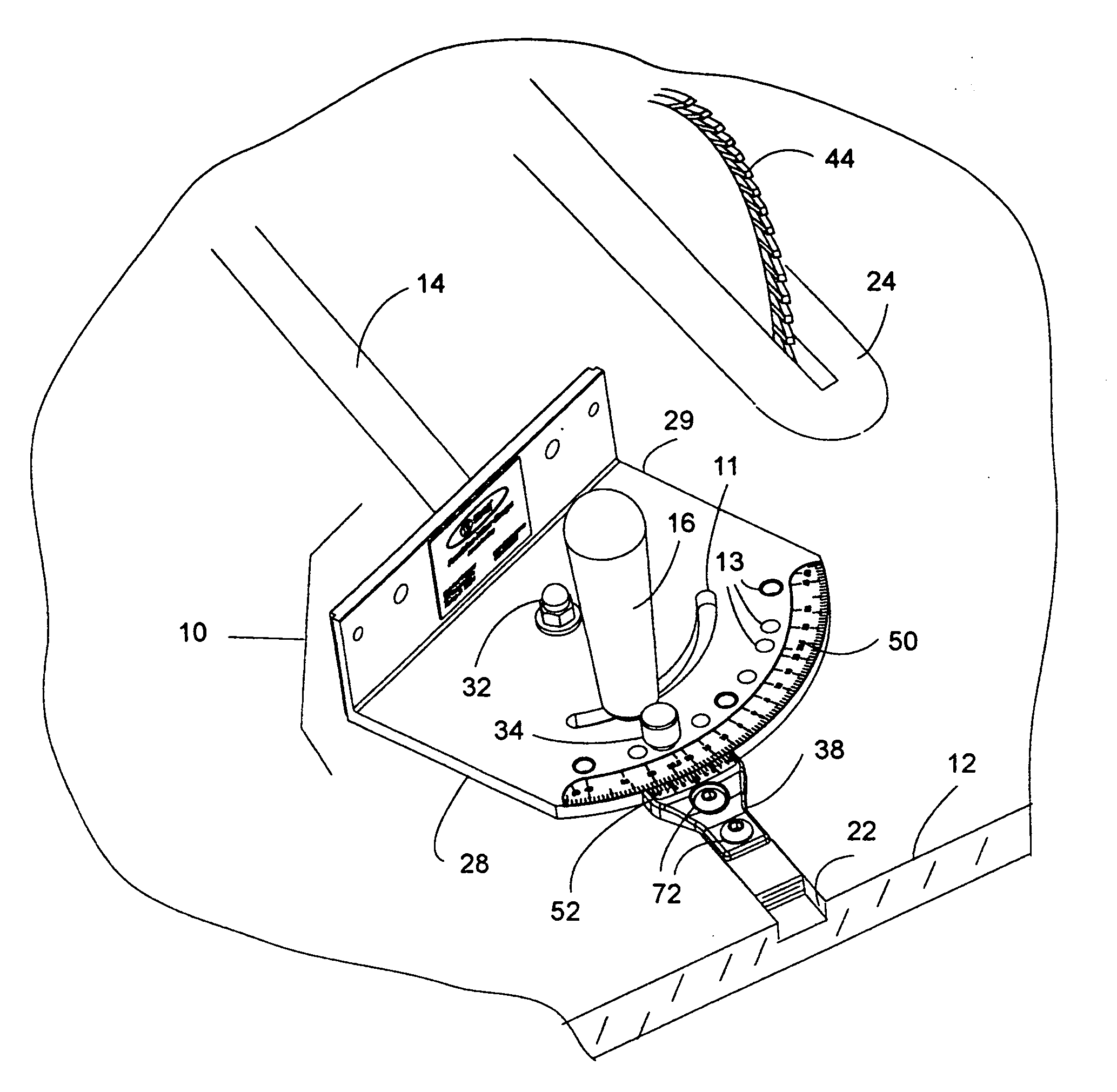
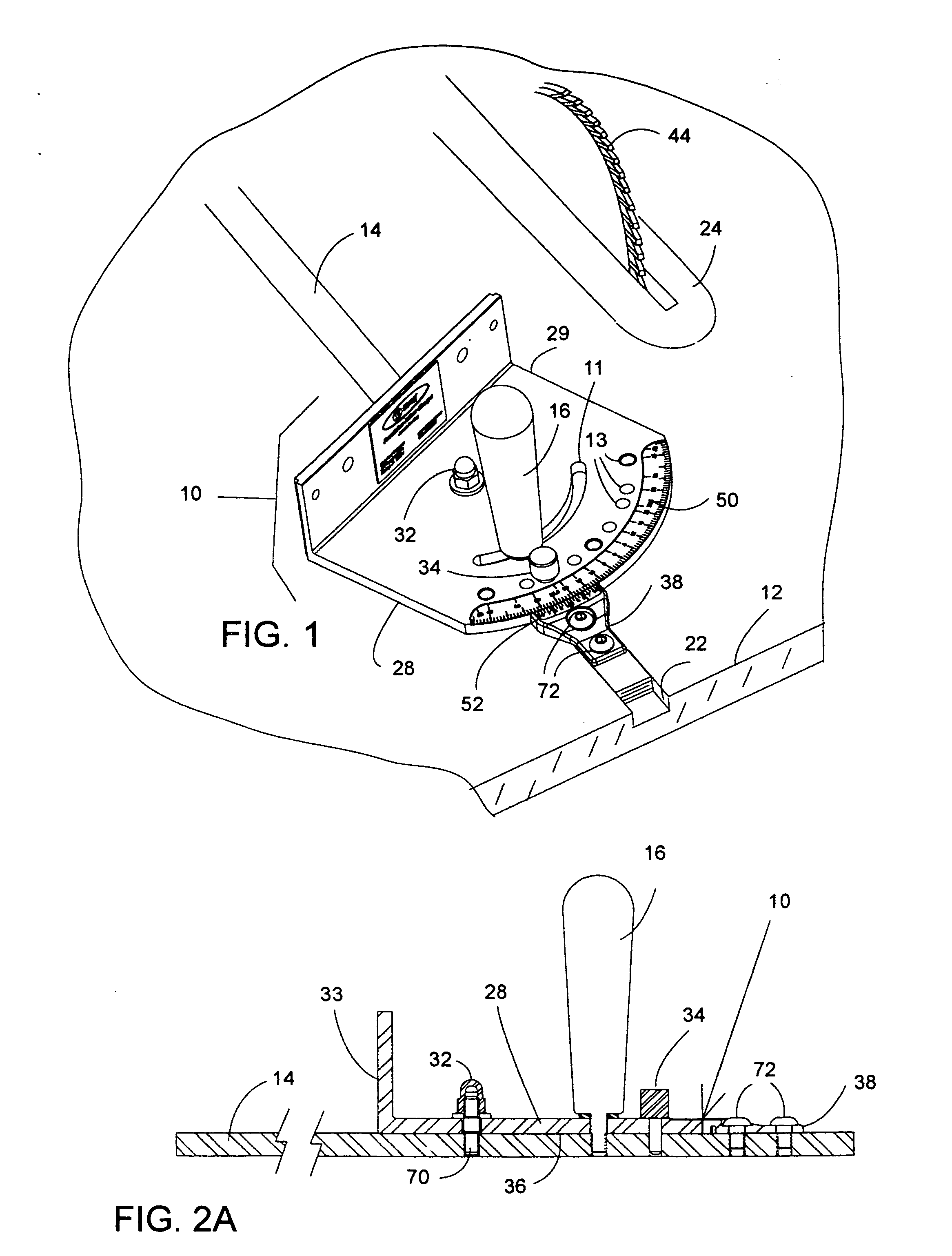
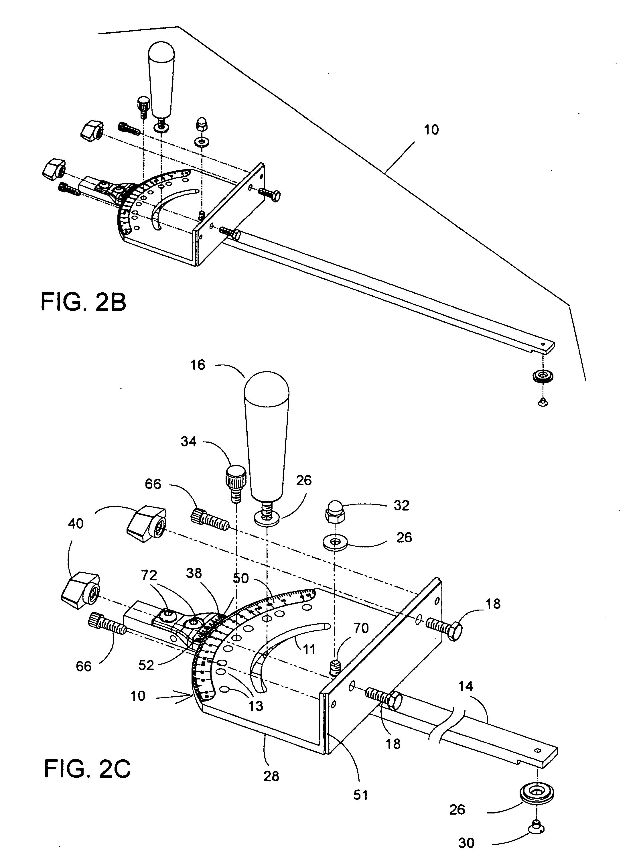
[0120]FIG. 1 illustrates a miter gauge 10 of the invention shown in a miter slot on a table saw. This is an improvement of the miter gauge in U.S. Pat. No. 5,337,641 and U.S. Pat. No. 5,768,966, the entire disclosures of which are hereby incorporated by reference for their teachings of how to make and use jigs and fixtures. The drawing is a perspective view of a miter gauge 10 with the miter bar 14 located in the table saw miter slot 22.

[0121] U.S. Pat. No. 5,768,966 discloses improved jigs and fixtures for aligning, guiding and or holding a workpiece as it is worked, for example as it is cut, drilled or routed. While the miter gauge disclosed in U.S. Pat. No. 5,768,966 represent a significant advance in the art, room still exists for improvements, particularly in the following respects:

[0122] The machined numerals of the '966 patent, which are expensive to manufacture, are replaced with a printed scale with a yellow background 50 for easy visibility with black lines and numbers t...


PUM

PropertyMeasurementUnit
angleaaaaaaaaaa
angleaaaaaaaaaa
anglesaaaaaaaaaa

Abstract

A miter gauge with a machined aluminum head that has a stamped aluminum scale secured in a machined slot. The scale has indicia that facilitate reading the scale including color-coded diamonds, arrow heads and longer lines at key positions. The miter gauge is quickly adjustable to 1/100th of a degree using ordinary shop tools such as a feeler gauge or dial caliper. An optional sled is a platform with two pieces of minitrack on each side and a dado in the middle in which the miter gauge can be secured quickly to a bar on the bottom of the sled that slides in the table saw miter gauge. A flip arm stop design with a removable back allows space for a zero clearance board on the front of an L-shaped fence extrusion. A T-shaped fence extrusion with a built-in zero-clearance board has a modified T-slot with an interlocking minitrack which allows the fence to be extended and secured with a standard bolt without the need for machining.

Description

CROSS-REFERENCE TO RELATED APPLICATION [0001] This application claims the benefit of U.S. Provisional Patent Application No. 60 / 581,798 filed on Jun. 22, 2004.STATEMENT CONCERNING FEDERALLY SPONSORED RESEARCH OR DEVELOPMENT [0002] Not applicable. FIELD OF THE INVENTION [0003] This invention relates to shop-made jigs and fixtures for positioning, aligning, guiding and / or holding a workpiece on metalworking or woodworking machines during a cutting or shaping operation. BACKGROUND OF THE INVENTION [0004] U.S. Pat. No. 5,768,966 (the '966 patent) and U.S. Pat. No. 6,880,442 disclose improved jigs and fixtures for aligning, guiding, and / or holding a workpiece as it is worked, for example, as it is cut, drilled, or routed. While the miter gauge disclosed in the '966 patent represents a significant advance in the art, room still exists for improvements, particularly in the following respects: [0005] The machined numerals of the '966 patent, which are very expensive to manufacture because t...

Claims


Application Information

Patent Timeline
Patent Type & Authority Applications(United States)
IPC IPC(8): B26D1/14B27B25/10B27B27/08
CPCB27B27/08B27B25/10Y10T83/7697
Inventor DUGINSKE, MARK A.
Owner ALLEN IP
Why Eureka
Try Eureka