Control apparatus for controlling vehicle drive apparatus, and vehicle drive system including the control apparatus

a technology of control apparatus and control apparatus, which is applied in the direction of electric propulsion mounting, transportation and packaging, gearing, etc., can solve the problems of limit to improving the generation efficiency and the rotational speed of the first electric motor, so as to reduce the electric energy consumed, maximize the generation efficiency of the first and second electric motors, and improve the fuel economy of the vehicle

Active Publication Date: 2005-12-22
TOYOTA JIDOSHA KK
View PDF10 Cites 22 Cited by
  • Summary
  • Abstract
  • Description
  • Claims
  • Application Information

AI Technical Summary

Benefits of technology

[0007] The present invention was made in the light of the background art discussed above. It is therefore a first object of the present invention to provide a control apparatus capable of maximizing an efficiency of generation of an electric energy while a vehicle drive apparatus is placed in its non-driving position, in the vehicle drive apparatus equipped with a differential mechanism serving as a speed variable transmission owing to its differential action. It is a second object of the invention to provide a vehicle drive system in which it is possible to maximize the efficiency of the electric energy generation while the drive apparatus is placed in its non-driving position. The first object may be achieved according to any one of first through eighth aspects of the invention which are described below. The second object may be achieved according to any one of ninth through twelfth aspects of the invention which are described below.
[0012] According to the fifth aspect of the invention, in the control apparatus defined in the third or fourth aspect of the invention, the generation controller controls the first and second electric motors during the generation of the electric energy, such that a total generation efficiency of the first and second electric motors is maximized.
[0020] In the control apparatus or drive system of each of the first through twelfth aspects of the invention, during the generation of the electric energy while the power transmitting path is being disconnected, namely, while the transmission is placed in its non-driving position, the switching device controller of the control apparatus places the differential mechanism in its differential state in which at least the second and third elements are rotatable at respective different speeds, rather than in its non-differential state in which at least the second and third elements are not rotatable at respective different speeds, namely, in which the first through third elements are rotated as a unit or in which the second element is not rotatable. The placement of the differential mechanism in its differential state provides a higher degree of freedom in determining the rotational speeds of the first and second electric motors which are connected to the second and third elements, respectively, thereby allowing the first and second electric motors to be operated at preferable operating points. That is, the control apparatus or drive system constructed according to the invention is capable of maximizing an efficiency of an electric energy generation as intended while the power transmitting path is being disconnected, in the vehicle drive apparatus equipped with the differential mechanism serving as a speed variable transmission owing to its differential action.
[0022] In the control apparatus of the fifth aspect of the invention, the generation controller is arranged to control the first and second electric motors during the generation of the electric energy, such that the overall generation efficiency of the first and second electric motors is maximized, thereby enabling the first and second electric motors to be operated at optimum operating points.
[0023] In the control apparatus of the sixth or seventh aspect of the invention, the pump controller is provided to control the electrically-operated hydraulic pump, such that the pressure of the working fluid supplied from the pump to the automatic transmission is reduced or substantially zeroed during the generation of the electric energy while the power transmitting path is being disconnected. This arrangement is effective to reduce the electric energy consumed by activation of the pump and improve a fuel economy of the vehicle.
[0024] In the control apparatus or drive system of each of the eighth, tenth and eleventh aspects of the invention, during the generation of the electric energy while the power transmitting path is being disconnected, the differential mechanism is placed in its continuously-variable shifting state as the differential state in which the differential mechanism functions as the continuously variable transmission permitting the ratio between the rotational speeds of the respective second and third elements to be continuously variable. In this arrangement, since the ratio between the rotational speeds of the respective second and third elements is continuously variable, the rotational speeds of the respective first and second electric motors connected to the respective second and third elements can be freely determined, whereby the operations of the first and second electric motors at desired operating points are facilitated.

Problems solved by technology

This means that the rotational speed of the first electric motor connected to the second element can not be freely determined, namely, the first electric motor as a generator can not be operated at such an operating point that maximizes the efficiency of the electricity generation.
That is, in the above-described hybrid vehicle drive apparatus, there is a limit to improvement of the generation efficiency.

Method used


Image

  • Control apparatus for controlling vehicle drive apparatus, and vehicle drive system including the control apparatus
  • Control apparatus for controlling vehicle drive apparatus, and vehicle drive system including the control apparatus
  • Control apparatus for controlling vehicle drive apparatus, and vehicle drive system including the control apparatus

Examples


Embodiment Construction

[0046] Referring first to FIGS. 1-18, there will be described in detail a first embodiment of the present invention.

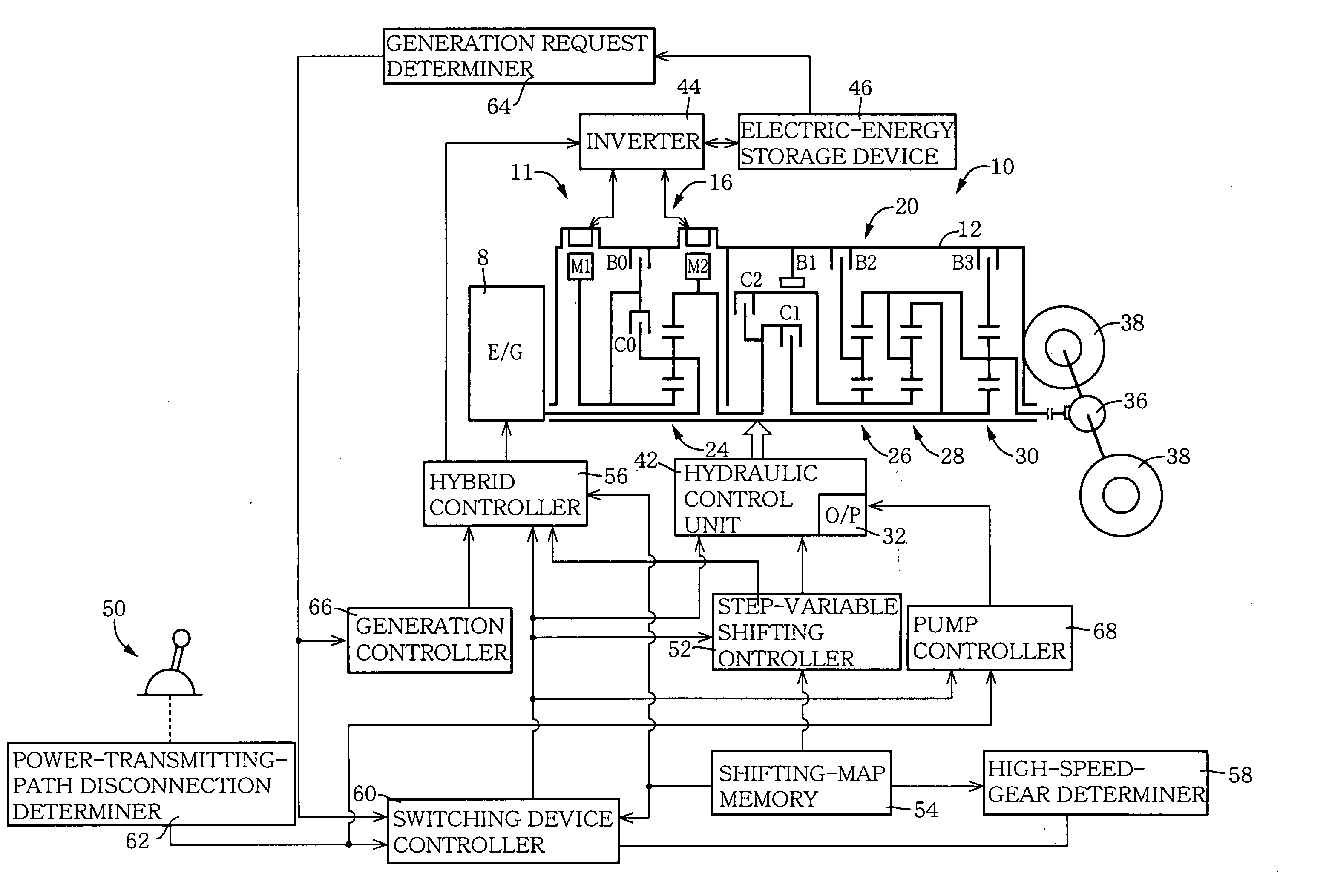
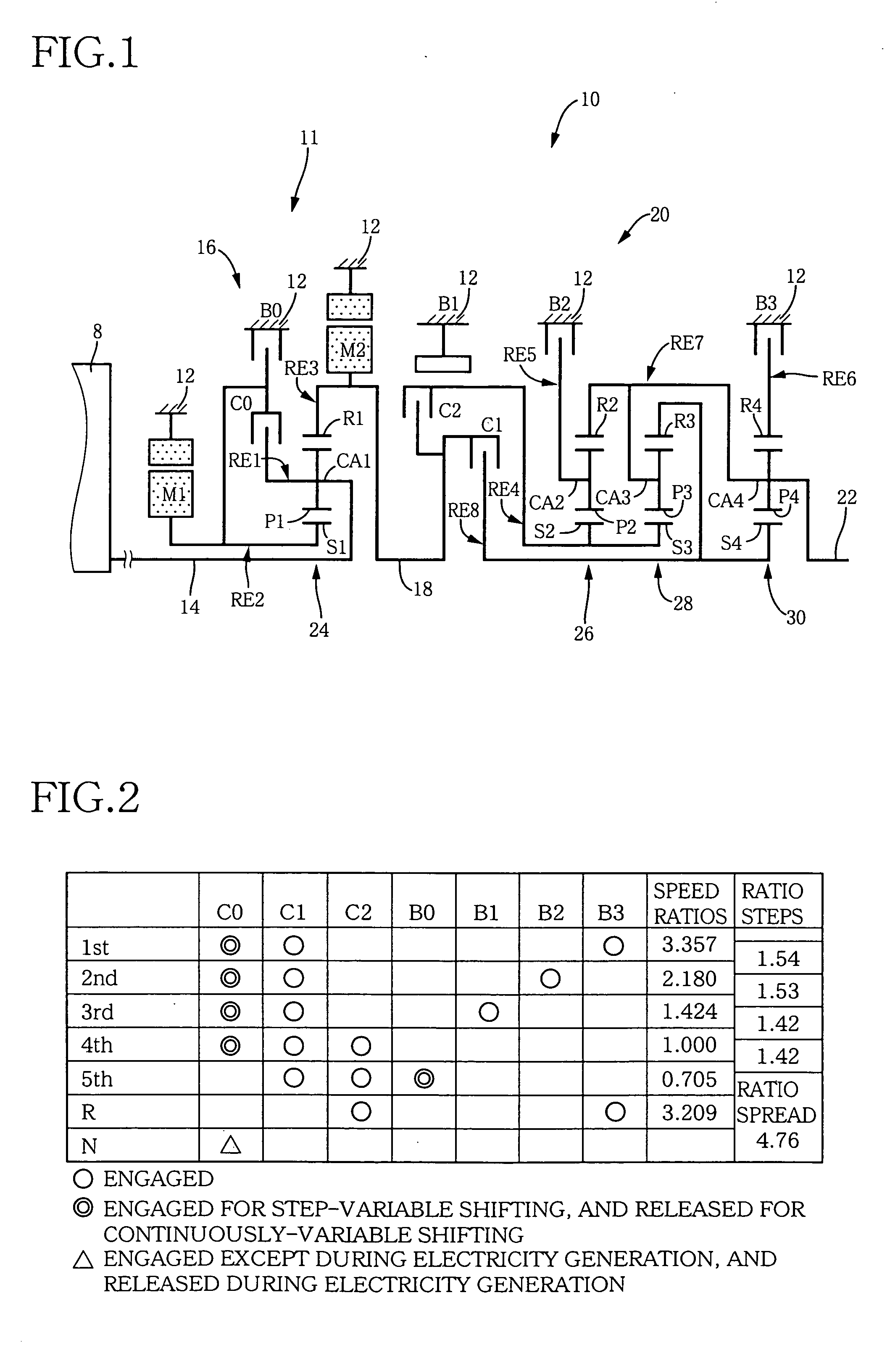
[0047]FIG. 1 is a schematic view showing a transmission mechanism 10 which constitutes a part of a drive apparatus for a hybrid vehicle. The transmission mechanism 10 includes: an input rotary member in the form of an input shaft 14 disposed on a common axis in a transmission casing 12 functioning as a stationary member attached to a body of the vehicle; a differential portion 11 connected to the input shaft 14 either directly, or indirectly via a pulsation absorbing damper or vibration damping device (not shown); a step-variable or multiple-step automatic transmission portion 20 interposed between and connected in series via a power transmitting shaft or member 18 to the differential portion 11 and a pair of drive wheels 38; and an output rotary member in the form of an output shaft 22 connected to the transmission portion 20. In this transmission mechanism 10, the i...


PUM


Abstract

A control apparatus for controlling a vehicle drive apparatus including: (i) a power transmitting member; (ii) a differential mechanism which has a first element connected to an engine, a second element connected to a first electric motor, and a third element connected to a second electric motor and the power transmitting member; (iii) an automatic transmission constituting at least a part of a power transmitting path between the power transmitting member and a drive wheel; and (iv) a differential-state switching device operable to selectively place the differential mechanism in its differential state in which the second and third elements are rotatable at respective different speeds, and in its non-differential state in which the second and third elements are not rotatable at respective different speeds. The control apparatus includes a switching device controller operable to cause the differential-state switching device to place the differential mechanism in the differential state, at least during generation of an electric energy by the first electric motor and / or second electric motor while the power transmitting path is being disconnected. Also disclosed is a vehicle drive system including the above-described control apparatus.

Description

[0001] This application is based on Japanese Patent Application No. 2004-168423 filed in Jun. 7, 2004, the content of which is incorporated hereinto by reference. BACKGROUND OF THE INVENTION [0002] 1. Field of the Invention [0003] The present invention relates in general to a control apparatus for controlling a vehicle drive apparatus which is equipped with a differential mechanism serving as a speed variable transmission owing to its differential action. More particularly, the invention is concerned with techniques for improving an efficiency of electricity generation while a drive power transmitting path is being disconnected. [0004] 2. Discussion of Related Art [0005] There is known a hybrid vehicle drive apparatus including: (i) a power transmitting member; and (ii) a differential mechanism having a first element connected to an internal combustion engine, a second element connected to a first electric motor having an electricity generating function, and a third element connecte...

Claims


Application Information

Patent Timeline
Patent Type & Authority Applications(United States)
IPC IPC(8): B60K1/02B60K6/26B60K6/365B60K6/445B60K17/04B60L50/16B60W10/08B60W10/10B60W10/26B60W10/30B60W20/00F16H3/72F16H61/00F16H61/02F16H61/68F16H61/684F16H61/686
CPCB60K1/02Y02T10/6239B60K6/445B60K6/547B60W10/08B60W10/11B60W20/00B60W30/19F16H3/728F16H2037/0873F16H2200/0043F16H2200/0047F16H2200/201F16H2200/2012Y10S903/911B60K6/365Y02T10/62B60W20/30
Inventor TABATA, ATSUSHITAGA, YUTAKA
Owner TOYOTA JIDOSHA KK
Why Eureka
Try Eureka