Hydraulic brake system for a wind energy plant

Inactive Publication Date: 2005-12-22
GENERAL ELECTRIC CO
View PDF20 Cites 12 Cited by
  • Summary
  • Abstract
  • Description
  • Claims
  • Application Information

AI Technical Summary

Benefits of technology

[0005] It is an object of the present invention to provide a hydraulic brake system for braking a rotating component, the brake syst

Problems solved by technology

In order to meet the requirements of rapid braking, a relatively large braking force should be applied, which may however lead to considerable vibrations and

Method used


Image

  • Hydraulic brake system for a wind energy plant
  • Hydraulic brake system for a wind energy plant
  • Hydraulic brake system for a wind energy plant

Examples


Example

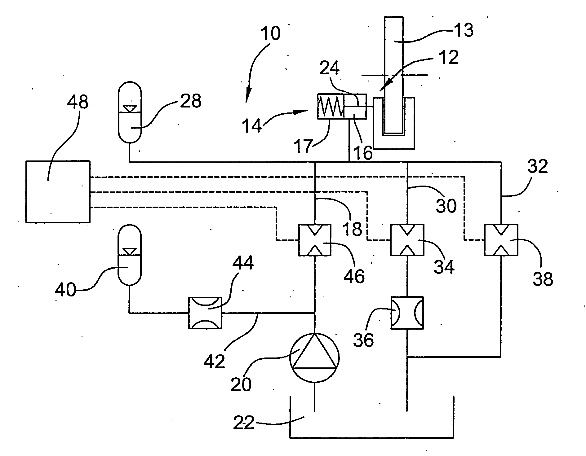
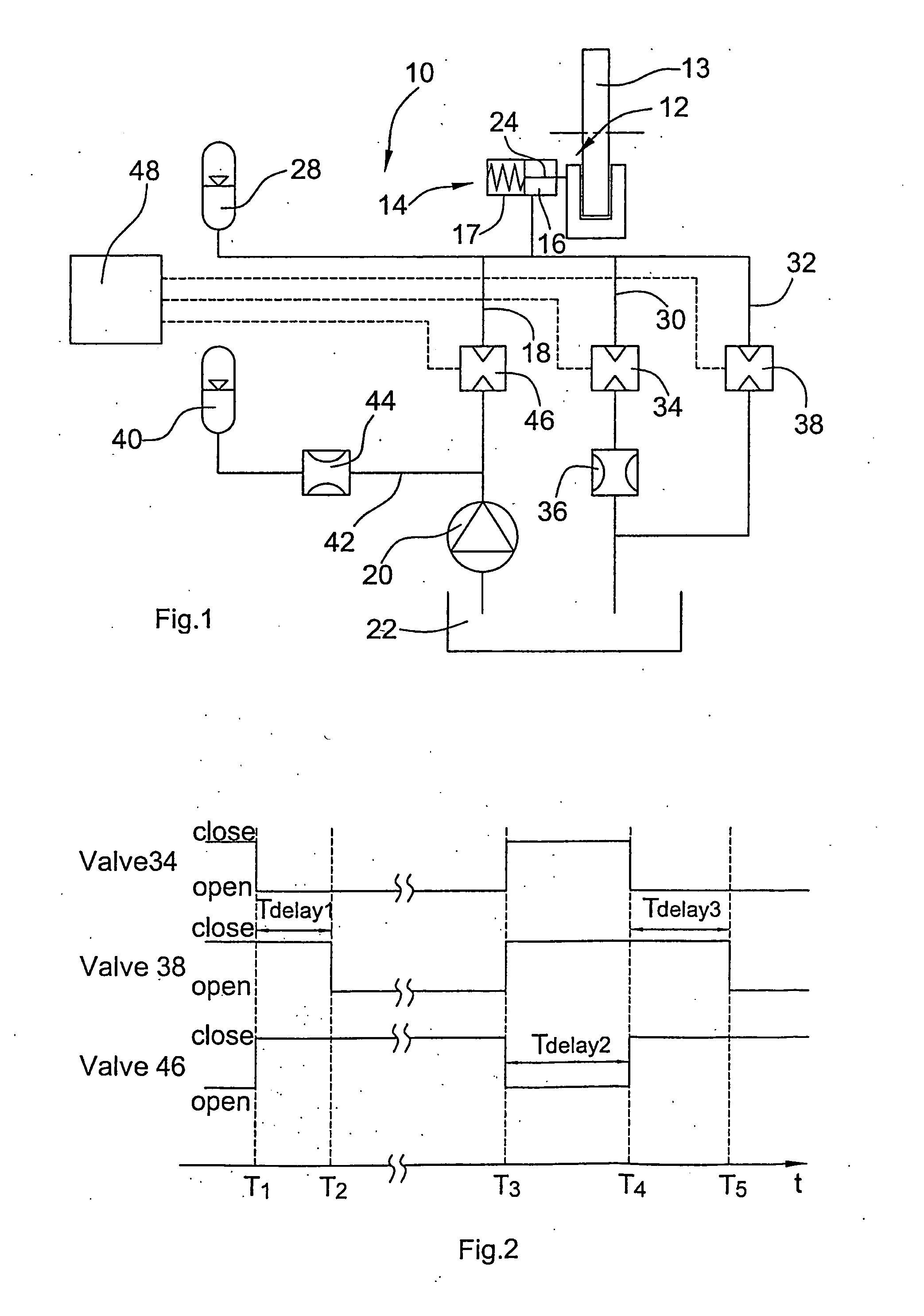
[0063]FIGS. 1 and 2 relate to a first embodiment of a hydraulic brake system 10. System 10 comprises a passive brake 12 for a—in this case, rotating—component 13 (e.g. brake disk on the rotor shaft of a wind energy plant) with one or a plurality of piston / cylinder units 14. The working volumes 16 of the cylinders 17 of the piston / cylinder unit 14 are supplied with pressurized working fluid from a reservoir 22 via a supply line 18 by means of a pump 20. The piston 24 of each piston / cylinder unit 14 is biased, e.g. by means of a spring 26, into the braking position actuating the brake 12, and can be moved against the biasing force into a release position by pumping working fluid into the working volume. Connected to the working volume 16 is a first storage means 28 storing such a quantity of pressurized working fluid that the overall volume of the brake piston and the storage means will always be sufficient to close the brake 12.

[0064] Connected to the working volume 16 of each pisto...


PUM


Abstract

The hydraulic brake system comprises a piston/cylinder unit (14) for activating and releasing a brake (12), comprising a volume (16) adapted to have a pressurized working fluid supplied thereto for moving the piston (24) from a braking position into a release position for releasing the brake. Further, the hydraulic brake system comprises a supply line (18) for the supply of working fluid from a reservoir (22), a discharge line (30) for the discharge of working fluid from the volume (16) of the piston/cylinder unit (14), a first valve (34) and an element (36) for determining the flow resistance, a bypass line (32) provided with a second ON/OFF valve (38) and arranged for a flow in parallel to the discharge line (30). At the start of a braking process, among the two ON/OFF valves (34,38) which in the released condition of the brake are in the closed condition, the first ON/OFF valve (34) is opened and, upon lapse of a presettable first time period (Tdelay1) from the opening of the first ON/OFF valve (34), the second ON/OFF valve (38) is opened.

Description

FIELD OF THE INVENTION [0001] The invention relates to a hydraulic brake system for braking a moving component of a wind energy plant, such as the brake disk of the power train or the azimuth drive of the wind energy plant. BACKGROUND OF THE INVENTION [0002] In several technical applications hydraulic brake systems are used, wherein, in particular in cases of emergency, a rotating component must for reasons of safety be braked down to a standstill within a very short period of time. An example of such a technical application is a wind energy plant whose rotor must be very rapidly braked in the case of malfunctions. [0003] In order to meet the requirements of rapid braking, a relatively large braking force should be applied, which may however lead to considerable vibrations and excessive dynamic load peaks in the system to be braked. This, in turn, may cause damage to the system and lead to relatively large material fatigue and aging. [0004] From WO-A-98 / 23474 a hydraulic brake syste...

Claims


Application Information

Patent Timeline
IPC IPC(8): B60T13/22F03D7/02
CPCB60T13/22F03D7/0248Y02E10/723F05B2260/902F05B2260/406Y02E10/72
Inventor UPHUES, ULRICH
Owner GENERAL ELECTRIC CO
Why Eureka
Try Eureka