Apparatus and method for diffused aeration

a diffused aeration and apparatus technology, applied in the field of apparatus and methods for diffused aeration, can solve the problems of reducing efficiency of fouled materials, and causing objectionable odors

Inactive Publication Date: 2005-12-22
HILLS BLAIR H
View PDF31 Cites 29 Cited by
  • Summary
  • Abstract
  • Description
  • Claims
  • Application Information

AI Technical Summary

Problems solved by technology

Even small quantities of hydrogen sulfide can produce objectionable odors thereby necessitating that oxygen be mixed into the liquid.
However, these porous materials are easily fouled and can become blocked when placed in dirty liquids, liquids having a high particulate concentration or high soluble mineral concentration.
Fouled materials reduce efficiency, increase operational energy cost, and increase bubble size.
Porous materials can also stretch over time, thereby increasing hole size and bubble formation diameter, or harden, thereby causing increased pressure.
Larger bubbles, caused by larger hole size, increased pressure or fouling, reduce the available gas-liquid surface area, which reduces the overall Standard Aeration Efficiency (SAE).
Periodic cleaning and maintenance often involve expensive and hazardous HCl injections into the diffuser system and / or the emptying of the aeration vessel followed by physical cleaning.
Plastic membranes must be periodically changed, which increases labor, materials and processing costs associated with an aeration system shut-down during installation.
Their efficiency, even when clean, is frequently reduced by the intensity of the liquid mixing.
Other traditional mechanical diffused aeration systems do not use a compressor, however, these systems require a vortex or a venturi system to create gas pockets at some depth below the surface of the liquid.
However, surface aerators achieve low gas utilization and require large volumes of gas to be mixed with liquid, causing a high rate of off-gassing, which strips volatile organics from the liquid into the gas.

Method used


Image

  • Apparatus and method for diffused aeration
  • Apparatus and method for diffused aeration
  • Apparatus and method for diffused aeration

Examples


example 1

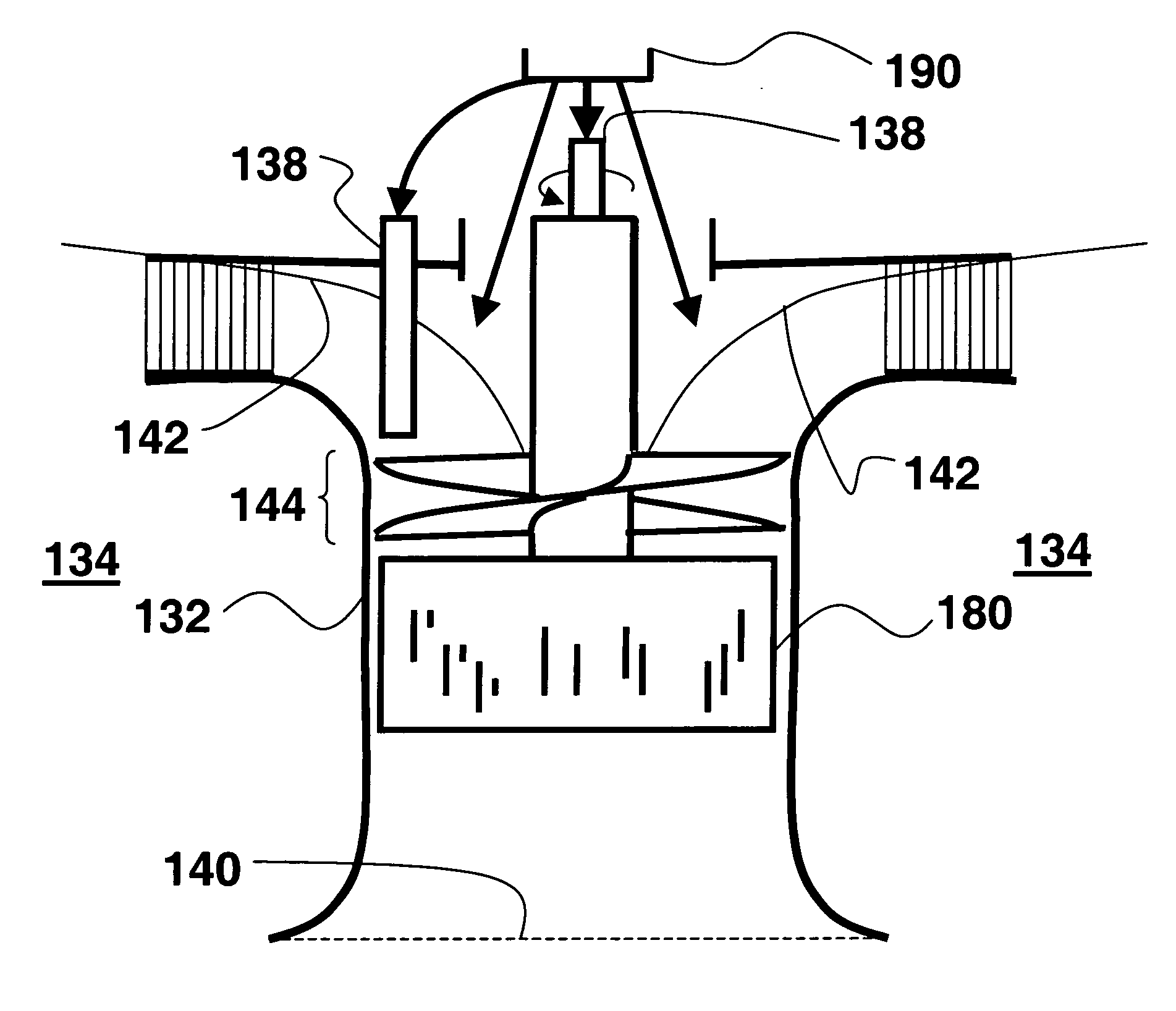
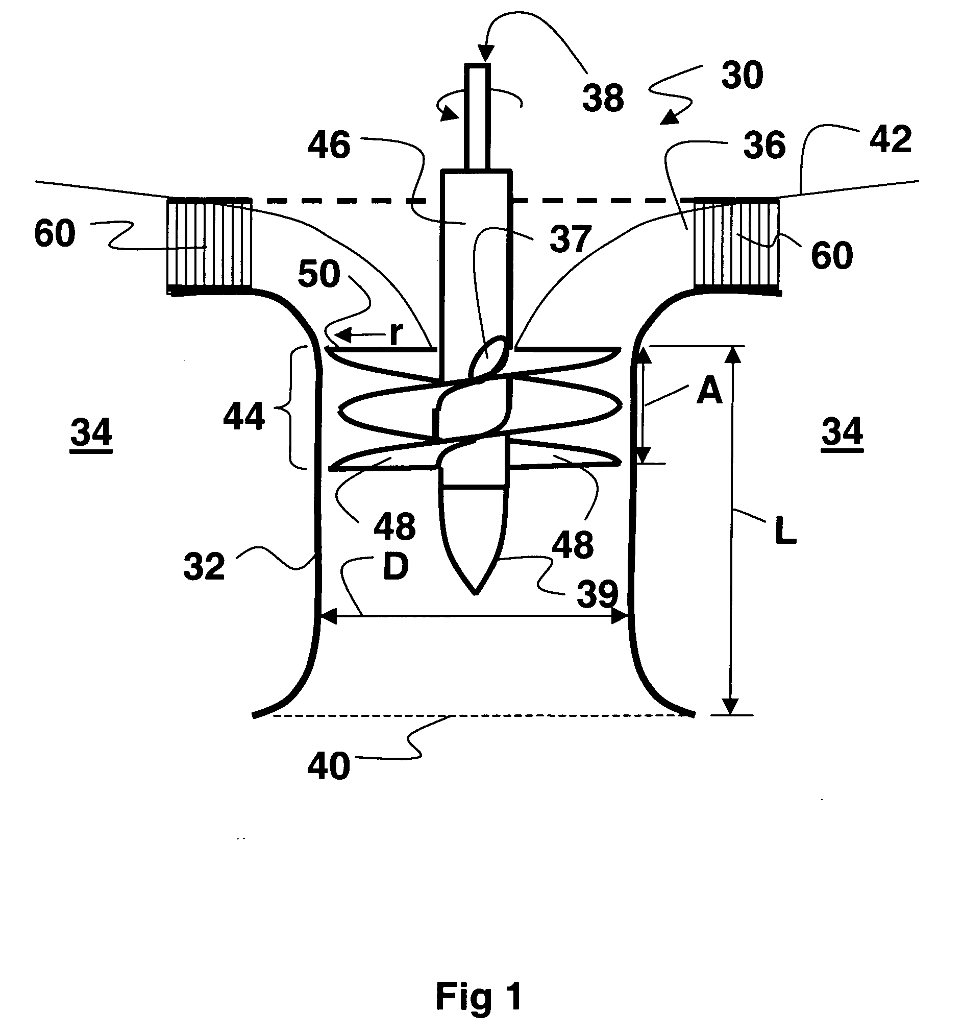
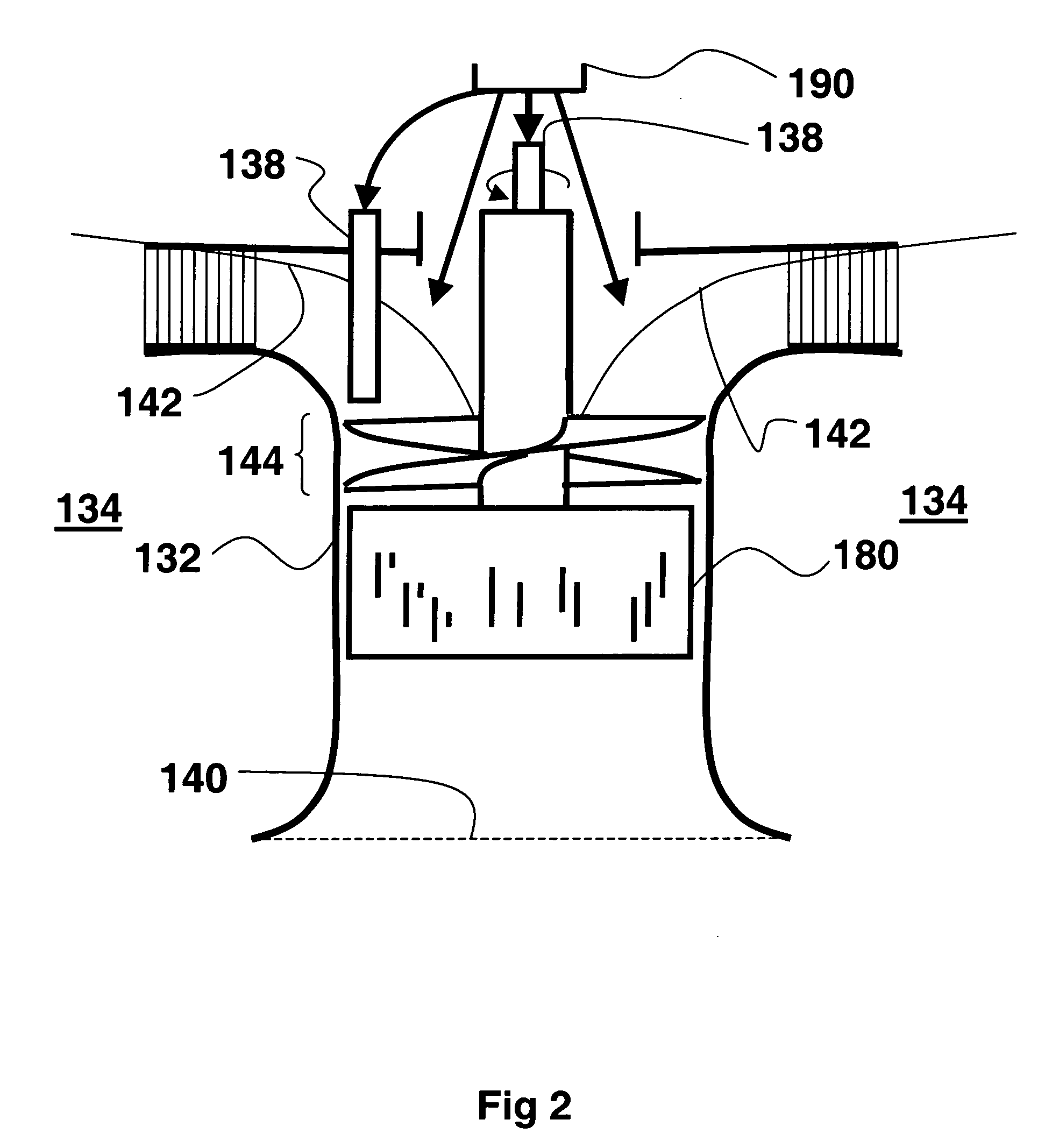
[0076] A 17 foot tank tube having a 10 foot diameter was filled with water to a depth of 16 feet. An impeller having a diameter of 29 inches with blades having a hollow cavity integral to the trailing edge was oriented to pump upwards in the vertical direction. The gas discharge was located at the trailing edge of the blades. The impeller had a pitch ratio of 0.42:1. The impeller was rotated at 230 rpm and was positioned 7 inches below the surface of the water in a draft tube having a diameter of 30 inches. The liquid inlet to the draft tube was fed water from the bottom of the tank through the 30 inch draft tube. The liquid inlet to the draft tube was fed water from the bottom of the tank through the 30 inch draft tube. The discharge of the draft tube was directed through a mixed gas-liquid outlet comprising a 42 inch tube that terminated 2.5 feet above the liquid level and was covered by a dish shaped top. The mixed gas-liquid mixture was then piped down 180 degrees and directed v...

example 2

[0077] A 17 foot tall tank having a 10 foot diameter was filled with water to a depth of 16.5 feet. A 29 inch diameter impeller having a pitch ratio of 0.31:1, capable of rotating at 225 rpm and oriented to pump downwards in the vertical direction was positioned 14 inches below the water surface in a draft tube having a diameter of 30 inches. The draft tube conveyed pumped liquid with entrained gas bubbles to a depth of 16.25 feet and discharged the gas-liquid mixture at ⅓ foot above the bottom of the tank. In operation, the system transferred 3.6 kg / kWh (6.1 pounds of oxygen / hp-hr) from air into clean water based on ANSI / ASCE standard 2-91. On start up, the system exhibited an initial dwell time of greater than 30 seconds for bubbles in this system to break the surface of the water surrounding the draft tube at the above conditions. The rise of the tank's liquid level during operation due to the volume of incorporated gas was from between 0.25 to 0.33 feet.

[0078] Table 1 provides ...


PUM

PropertyMeasurementUnit
axis of rotationaaaaaaaaaa

Abstract

An apparatus for mixing gas and liquid is disclosed. The apparatus can comprise a draft tube having a gas inlet, a liquid inlet, a gas-liquid outlet, and an impeller rotatably mounted within the draft tube. The gas can be entrained into the liquid by rotation of an impeller having a low pitch ratio, such as less than 1:1. The impeller can have a diameter than is greater than the axial length of the impeller and can comprise at least one blade extending at least 30° around an axis of rotation of the impeller. Liquid turning vanes can also be positioned external to the draft tube to rotate liquid entering the draft tube in a direction opposite the direction of rotation of the impeller. The impeller can be constructed to create a reduced pressure zone, which directs gas axially downward within the draft tube upon rotation of the impeller.

Description

CROSS REFERENCE TO RELATED APPLICATION [0001] This application claims the benefit of U.S. Provisional Application No. 60 / 581,697 filed Jun. 21, 2004, which is incorporated herein by reference.FIELD OF THE INVENTION [0002] The present invention relates generally to gas-liquid mixers, and more particularly to a gas-liquid mixer that achieves diffused aeration by a mechanical aerator. BACKGROUND INFORMATION [0003] Gas-liquid mixing systems are conventionally used for many purposes, such as the mass transfer of gases into and / or out of liquids. Oxidation and reduction reactions often require that a gas, such as oxygen, chlorine or hydrogen, be mixed with liquids in the presence of solids. Unwanted gases dissolved in liquids can be stripped from the liquid by mixing a desired gas into the liquid. Direct contact heating of a liquid requires that a hot gas be mixed into a liquid, and, in some instances, the pH of a liquid can be adjusted by mixing a gaseous acid or base into the liquid. [0...

Claims


Application Information

Patent Timeline
Patent Type & Authority Applications(United States)
IPC IPC(8): B01F3/04B01F7/00B01F15/00
CPCB01F3/04539B01F3/04609B01F7/00341B01F7/00358B01F7/00633B01F2215/0422B01F2003/04546B01F2003/0456B01F2003/04567B01F2215/0409B01F7/166B01F23/23313B01F23/23311B01F23/23314B01F23/23341B01F23/2331B01F27/1132B01F27/113B01F27/191B01F27/84
Inventor HILLS, BLAIR H.
Owner HILLS BLAIR H
Why Eureka
Try Eureka