Mobile charger

Inactive Publication Date: 2005-12-22
ARTRANG
View PDF32 Cites 47 Cited by
  • Summary
  • Abstract
  • Description
  • Claims
  • Application Information

AI Technical Summary

Benefits of technology

[0032] The mobile charger in accordance with the present invention is characterized in that the output circuit unit within the inner circuit unit converts DC voltage boosted in the DC/DC converter circuit module to a constant voltage/current necessary for the drive power for the mobile phone and supplies the constant voltage/curr

Problems solved by technology

However, such a charger is inconvenient to carry during traveling or walking and requires AC 220V or 110V to provide an electric charge.
In addition, it is impossible to quickly charge batteries with the charger.
As for a quick charger, which is available in, for example, convenience stores, it incurs higher costs than does a charger in home.
Moreover, because batteries for different kinds of mobile phones are different in capacity, quick chargers supply excessive currents and thereby charge batteries in excess of their capacities, suffering from the disadvantage of generating heat in the batteries or giving rise to a reduction in life span or a malfunction.
Partic

Method used


Image

  • Mobile charger
  • Mobile charger
  • Mobile charger

Examples


Example

[0073] Below, both the first and the second embodiment will be explained with emphasis on the outer housing and connector joining structure of the present invention.

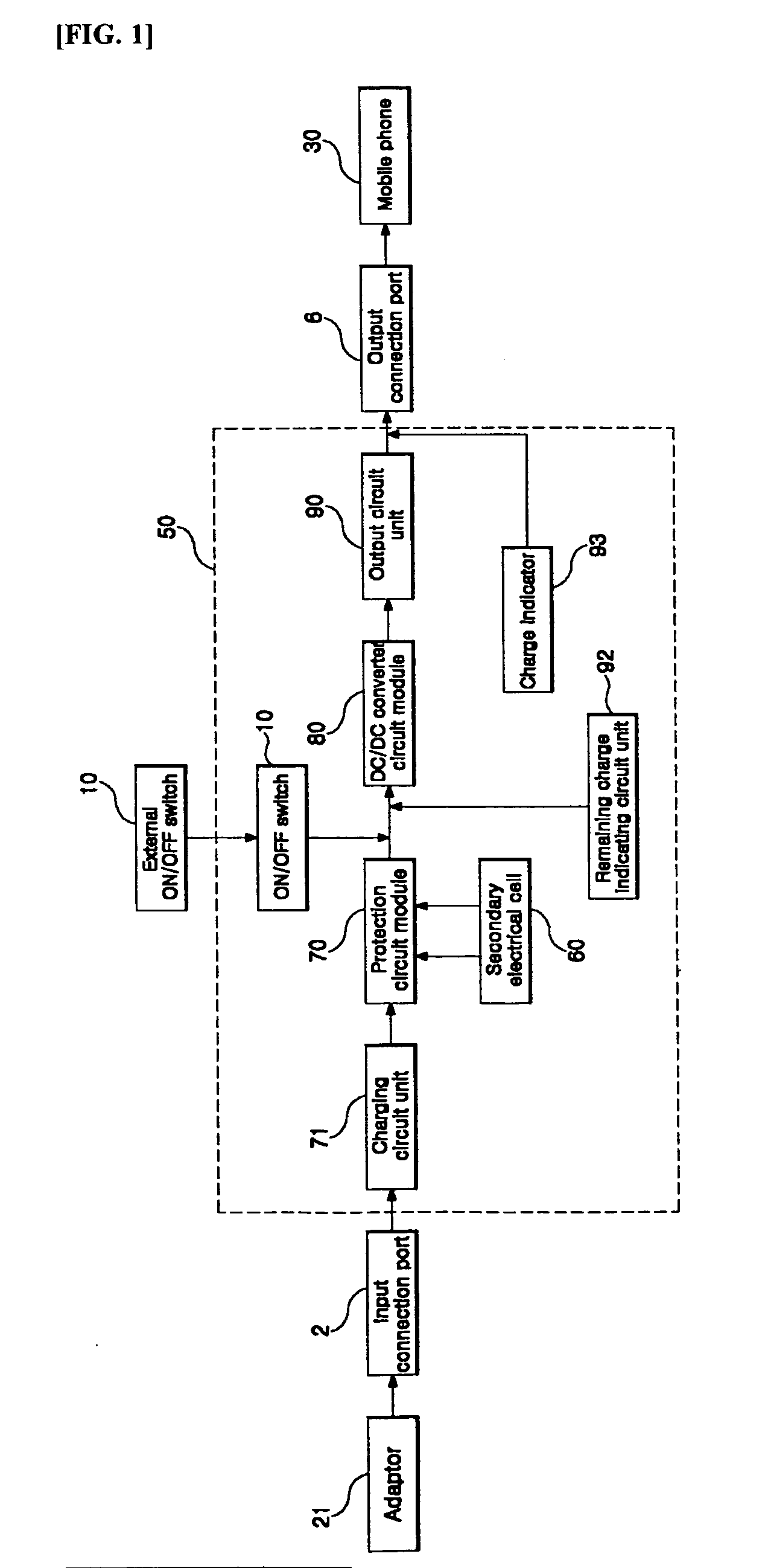
[0074] A housing 1 for accommodating the inner circuit unit 50 and the secondary electrical cell 60 is shown in a front view in FIG. 5 and in a side view in FIG. 7, in accordance with the first embodiment of the present invention. FIGS. 6 and 8 show a housing I according to the second embodiment of the present invention in a front view and a perspective view, respectively. FIG. 9 is a side view showing a housing structure that is employed in both of the embodiments.

[0075] As seen in the drawings, the housing 1 comprises an upper housing pane 1a and a lower housing pane 1b, which are fixedly combined with each other by a fixture. The housing 1 has a diameter ranging from 6 to 8 cm such that it can be held in one hand. In one side of the housing 1, the input connection port 2 is provided for an input cable 18 extending f...

Example

[0082]FIG. 14 shows a mobile charger according to the first embodiment of the present invention, applied to a mobile phone 30.

[0083] In the first embodiment, the mobile charger and the mobile phone are connected to each other through an output cable 14. Responsible for the transfer of data from / to and the supply of power to the mobile phone, one end of the output cable 14 is connected with an external connector provided with a plurality of contact pins. The other end of the output cable 14, having a cylindrical protrusion shape 16, is connected to the output connection port 6 of the housing 1. Correspondingly, the output connection port 6 has an output groove 7 formed therein, into which the cylindrical protrusion shape 16 is inserted, whereby the output groove 7 is electrically connected to the inner circuit unit 50 to supply a constant current and a constant voltage to an interior circuit of the mobile phone through the output cable 14.

[0084]FIG. 15 shows a mobile charger accord...


PUM


Abstract

Disclosed herein is a convenient and economical mobile charger, which is small enough to be held in one hand and can electrically charge a portable electronic device by using an embedded secondary electrical cell to which electric power is supplied, particularly through an external connector functioning to transfer data to/from the electronic device, whereby the portable electronic device can be charged with improved convenience, anytime and anywhere.

Description

RELATED APPLICATIONS [0001] The present disclosure relates to subject matter contained in priority Korean Application No. 10-2004-0045983, filed on Jun. 21, 2004, which is herein expressly incorporated by reference in its entirety. BACKGROUND OF THE INVENTION [0002] 1. Field of the Invention [0003] The present invention relates to a mobile charger. More particularly, the present invention relates to a convenient and economical mobile charger, which is small enough to be held in one hand and can electrically charge a portable electronic device by using an embedded secondary electrical cell to which electric power is supplied, particularly through an external connector functioning to transfer data to / from the electronic device, whereby the portable electronic device can be charged with improved convenience, anytime and anywhere. [0004] 2. Description of the Related Art [0005] A Mobile or cellular phone, which may now be one of the most indispensable necessities of life, has evolved fr...

Claims


Application Information

Patent Timeline
IPC IPC(8): H01M10/46H01M10/48H01R27/02H01R31/06H02J7/00H02J7/02H02M3/155
CPCH01M10/46H01M10/488H02J7/0054H01R31/065H02J7/0042H01R27/02H02J7/342Y02E60/10H02J7/0047H02J7/0029H02J2207/20
Inventor LEE, SANG-SHINSONG, JIN-SUSHIM, WOO-JUCHEON, KI-CHEOL
Owner ARTRANG
Why Eureka
Try Eureka