

Image heating apparatus and heater therefor
- Summary
- Abstract
- Description
- Claims
- Application Information
AI Technical Summary
Benefits of technology
Problems solved by technology
Method used
Image

Examples
example 1
(1) Example of Image Forming Apparatus
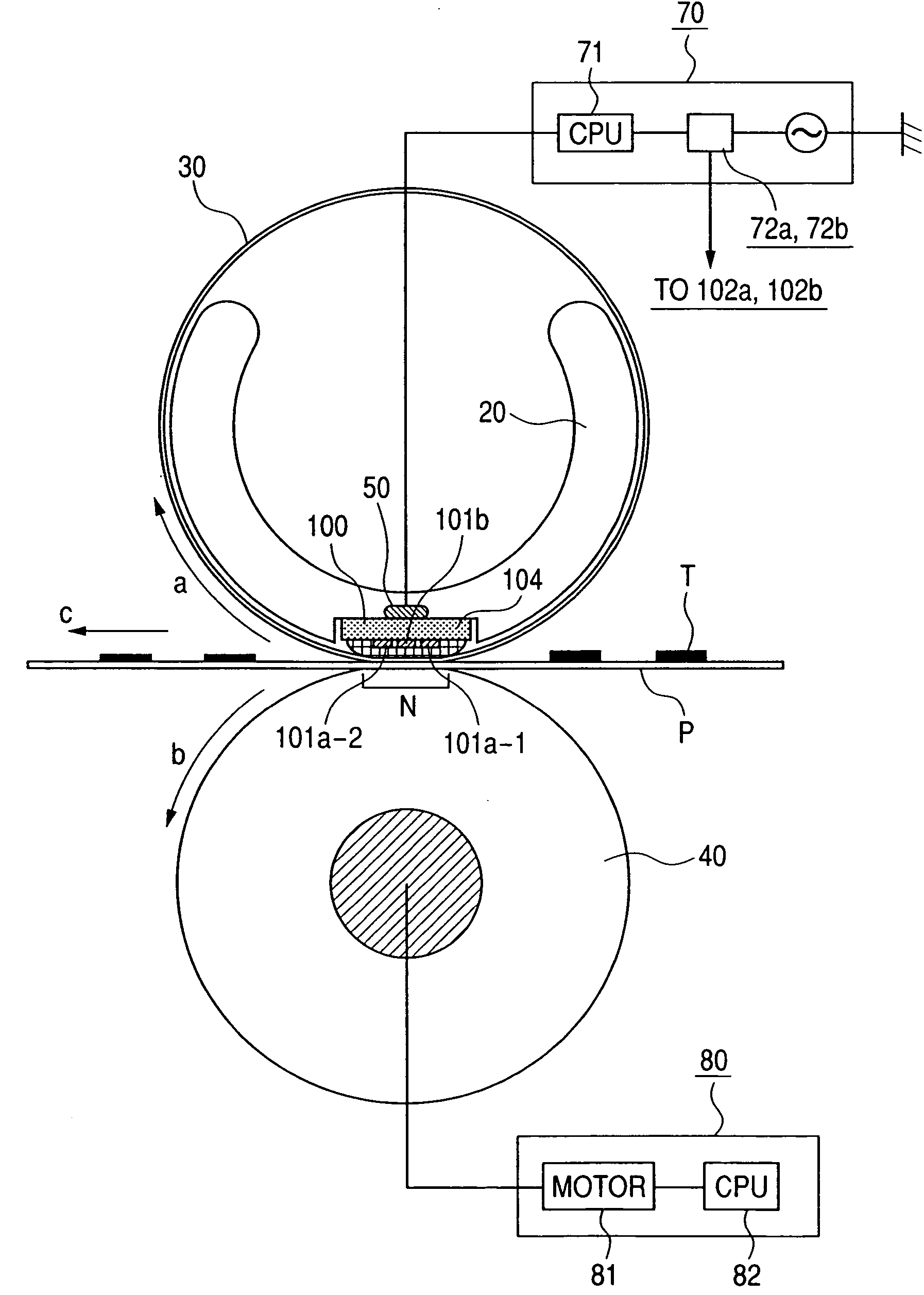
[0059]FIG. 11 shows an image forming apparatus equipped with an image heating-fixing apparatus (hereinafter represented as fixing apparatus) as an image heating apparatus of the present invention. The image forming apparatus shown therein is a laser beam printer utilizing an electrophotographic process.
[0060] The image forming apparatus is provided with an electrophotographic photosensitive member of drum shape (hereinafter represented as photosensitive drum) as an image bearing member. The photosensitive drum 1 is rotatably supported in a main body M of the apparatus, and is rotated at a predetermined process speed in a direction R1 by drive means (not shown).
[0061] Around the photosensitive drum 1 and along a rotating direction thereof, there are provided in succession a charging roller (charging apparatus) 2, exposure means 3, a developing apparatus 4, a transfer roller (transfer apparatus) 5 and a cleaning apparatus 6.
[0062] In a lower ...
example 2
[0107] The effects of the example 1 can also be attained in a configuration of example 2 shown in the following.
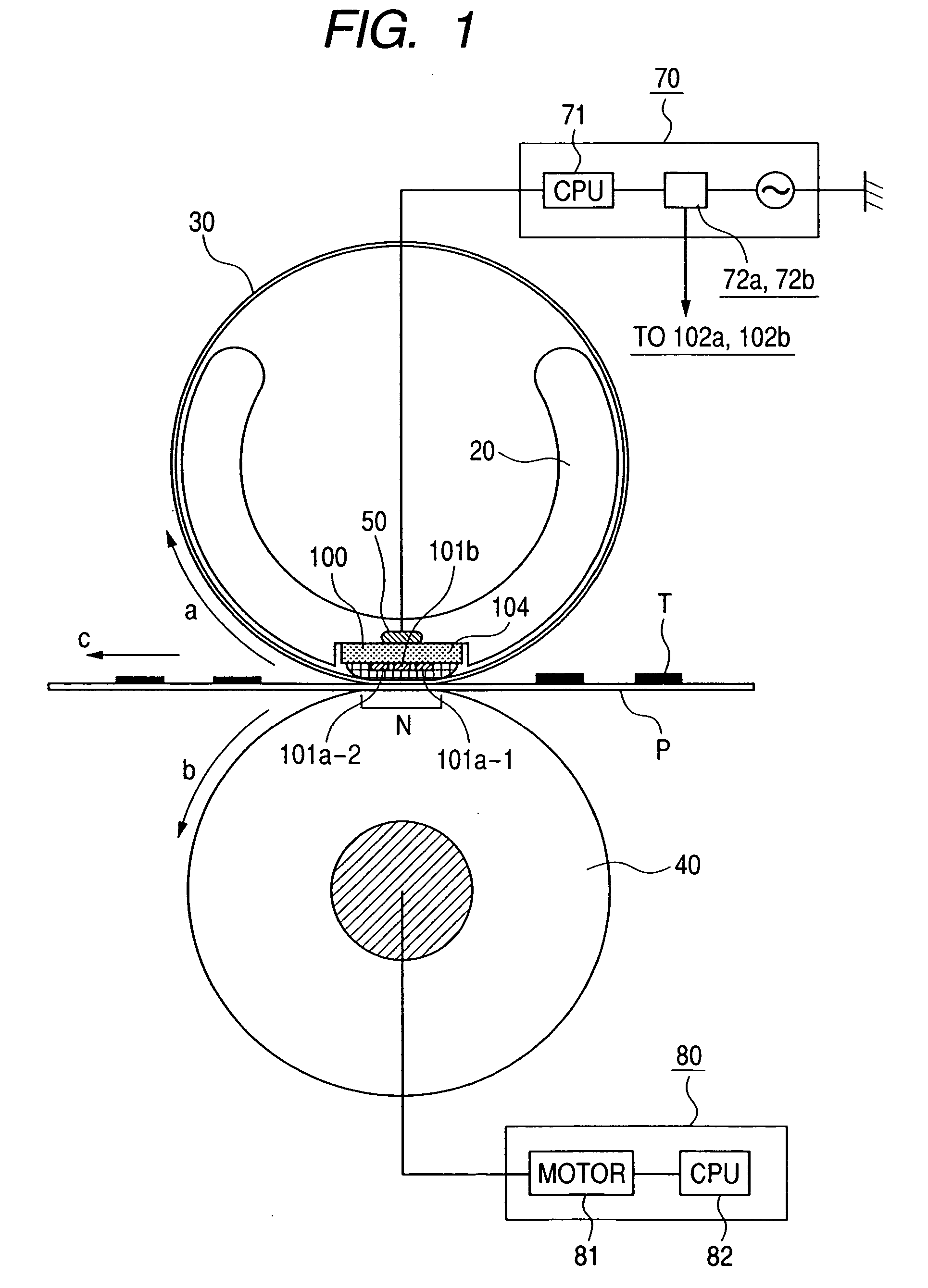
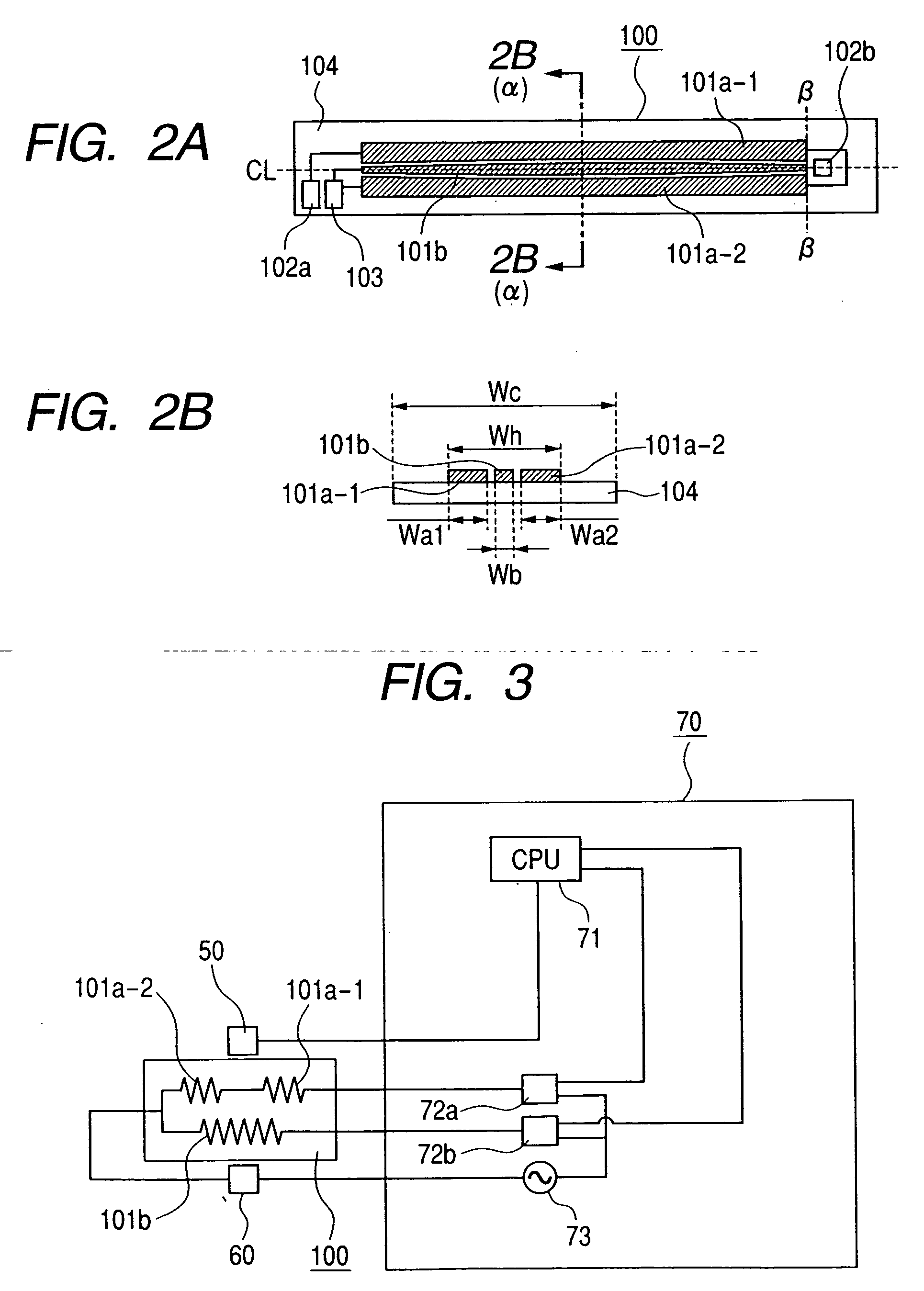
[0108]FIGS. 6A and 6B schematically illustrate a configuration of a heater 200 of the present example 2. The heater 200 is provided with heat generating patterns 201a-1, 201a-2 (first heat generating resistors) on both edge sides in the direction of width (shorter side direction) of a heater substrate 204, and a heating generating pattern 201b (second heat generating resistor) therebetween. Among these heat generating patterns 201a-1, 201a-2 and 201b, the heat generating patterns 201a-1, 201a-2 are mutually connected in parallel to constitute a first conductive path between a current supply electrode 202a and a common electrode 203. The heat generating pattern 201b constitutes a second conductive path between a current supply electrode 202b and the common electrode 203. The heat generating patterns 201a-1, 201a-2 (first heat generating resistors) are driven by a triac 72a...
example 3
[0119] The effects of the examples 1 and 2 can also be attained in a configuration of example 3 shown in the following.
[0120] In the examples 1 and 2, there have been explained a fixing apparatus having a reference position of sheet passing at the center of the longitudinal direction and a heater provided therein. The present example 3 shows an embodiment of a fixing apparatus having a reference position of sheet passing provided at an end portion (longitudinal end) in the longitudinal direction (direction perpendicular to the conveying direction c of the recording material P), and a heater to be provided therein.
[0121]FIG. 9 shows a heater configuration to be provided in a fixing apparatus having a reference position of sheet passing at a longitudinal end portion. Configurations other than the heater configuration are same as those in the examples 1 and 2. The heater 300 is provided with heat generating patterns 301a-1, 301a-2 (first heat generating resistors) on both edge sides ...
PUM
 Abstract
Description
Claims
Application Information