Magnetic sensing device with multilayered pinned magnetic layer having magnetostriction-enhancing layer

a multi-layered, magnetic layer technology, applied in the field of magnetic sensing devices, can solve the problems of reducing the gmr effect, the structure cannot appropriately respond to the increasing recording density of recording media, and the cpp-type magnetic sensing device cannot be sufficiently improved, etc., to achieve stable magnetization of the pinned magnetic layer, distortion and asymmetry of reproduced waveforms, and high reliability

Active Publication Date: 2005-12-22
TDK CORPARATION
View PDF6 Cites 1 Cited by
  • Summary
  • Abstract
  • Description
  • Claims
  • Application Information

AI Technical Summary

Benefits of technology

[0061] As a result, magnetization of the pinned magnetic layer is more effectively pinned in the height direction. Therefore, distortion and asymmetry of reproduced waveforms, caused by disordered magnetization of the pinned magnetic layer by the longitudinal bias magnetic field from the hard bias layers, are decreased; inversion of the pinned magnetic layer caused by mechanical stress or the like can be prevented; and stable magnetization of the pinned magnetic layer can be also maintained regardless of a change in stress. ...

Problems solved by technology

In conventional magnetic sensing devices, the presence of very thick antiferromagnetic layers causes disadvantages, such as a decrease in a giant magnetoresistive (GMR) effect.
As a result, the CPP-type magnetic sensing device cannot be sufficiently improved in the GMR effect which is typified by a resistance change per unit area (ΔR·A).
Therefore, the structure cannot appropriately respond to the increasing recording density of recording media.
These problems similarly occur in the magnetic...

Method used


Image

  • Magnetic sensing device with multilayered pinned magnetic layer having magnetostriction-enhancing layer
  • Magnetic sensing device with multilayered pinned magnetic layer having magnetostriction-enhancing layer
  • Magnetic sensing device with multilayered pinned magnetic layer having magnetostriction-enhancing layer

Examples


Embodiment Construction

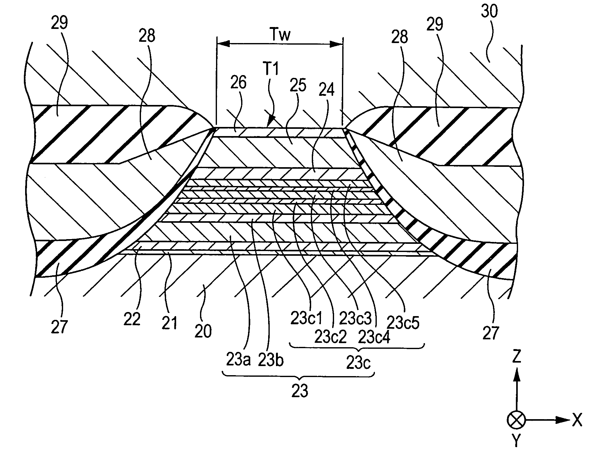
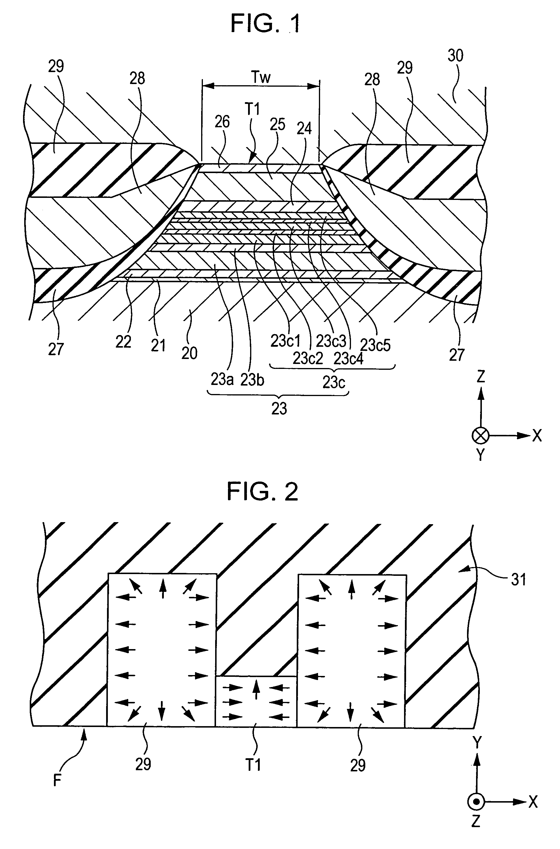
[0076]FIG. 1 is a cross-sectional view of a magnetic sensing device according to a first embodiment of the present invention, viewed from a side facing a recording medium. FIG. 4 is a partial schematic view of the magnetic sensing device shown in FIG. 1.

[0077] In the magnetic sensing device shown in FIGS. 1 and 4, a multilayer material T1 is disposed on a bottom shielding layer 20 made of a magnetic material.

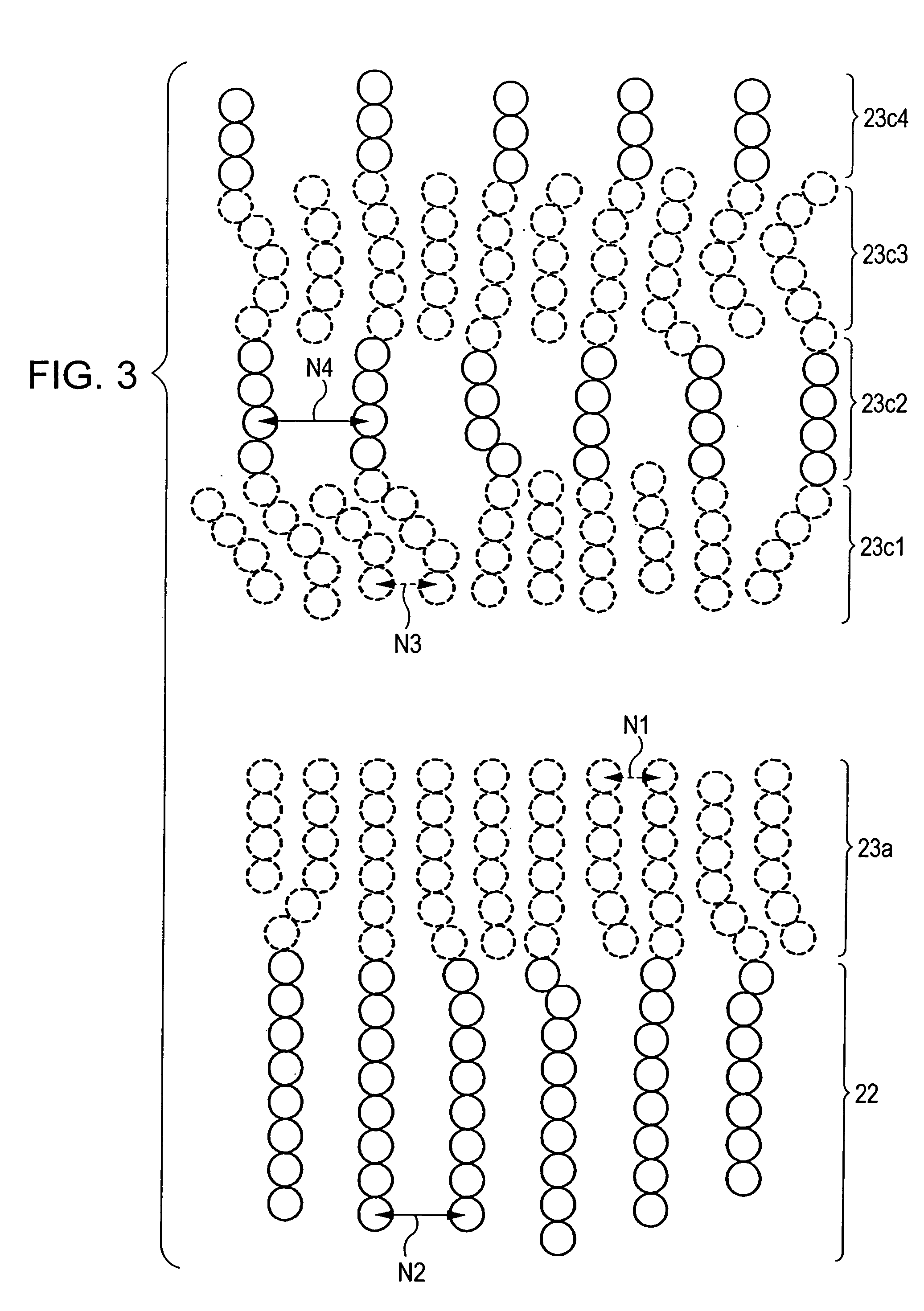
[0078] In the magnetic sensing device shown in FIGS. 1 and 4, the multilayer material T1 is a composite composed of a seed layer 21, a first magnetostriction-enhancing layer 22, a pinned magnetic layer 23, a nonmagnetic material layer 24, a free magnetic layer 25, and a protective layer 26 in this order from the bottom.

[0079] The seed layer 21 is made of a Ni—Fe alloy, a Ni—Fe—Cr alloy, Cr, Ta, or the like. For example, the seed layer 21 is made of 60 atomic % Ni0.8Fe0.2 and 40 atomic % Cr, with a thickness of 35 to 60 Å.

[0080] The presence of the seed layer 21 improves (111...


PUM


Abstract

A magnetic sensing device is presented that has a multilayer material with a pinned magnetic layer, a nonmagnetic material layer, and a free magnetic layer. The pinned magnetic layer is a composite with a nonmagnetic intermediate layer and magnetic thin-film layers separated from each other by the nonmagnetic intermediate layer. A first nonmagnetic magnetostriction-enhancing layer is on the pinned magnetic layer and contacts a first thin-film layer placed farthest from the nonmagnetic material layer. At least one of the magnetic thin-film layers has a composite structure with a second nonmagnetic magnetostriction-enhancing layer and magnetic layers separated from each other by the second magnetostriction-enhancing layer. All of the magnetic layers are magnetized in the same direction antiparallel to the adjacent magnetic thin-film layer. At least some crystals of the first and second magnetostriction-enhancing layers and the first thin-film layer/magnetic layers are epitaxial or heteroepitaxial.

Description

BACKGROUND OF THE INVENTION [0001] 1. Field of the Invention [0002] The present invention relates to magnetic sensing devices which can strongly pin magnetization of pinned magnetic layers by uniaxial anisotropy of the pinned magnetic layers themselves. [0003] 2. Description of the Related Art [0004] Magnetic sensing devices including multilayer materials each formed by laminating a free magnetic layer, a nonmagnetic material layer, and a pinned magnetic layer are classified into two types depending on the current direction with respect to the multilayer materials; i.e. a current-in-the-plane (CIP) type and a current-perpendicular-to-the-plane (CPP) type. [0005] In the CIP-type magnetic sensing devices, current is applied to the multilayer materials in the direction parallel to the film surfaces. On the other hand, in the CPP-type magnetic sensing devices, current is applied in the direction perpendicular to the film surfaces of the multilayer materials. [0006] The CPP-type magnetic...

Claims


Application Information

Patent Timeline
IPC IPC(8): G01R33/09G11B5/127G11B5/33G11B5/39
CPCB82Y10/00B82Y25/00G11B2005/3996G11B5/3932G01R33/093
Inventor HASEGAWA, NAOYASAITO, MASAMICHIUMETSU, EIJI
Owner TDK CORPARATION
Why Eureka
Try Eureka