[0015] Additionally, prior automated optical inspection techniques are generally inflexible in that differences in the captured image that are of no consequence may result in a variation that either needs a template to reflect such variance as being acceptable or that causes the part to fail its inspection. For instance, differences in illumination may vary the brightness of portions of the captured image from the brightness of corresponding portions of a template, but such variations in brightness are not indicative of a problem in the object under inspection. As another example, a component of the object under inspection that is a different color (e.g., is painted a different color) than that of the corresponding component used in the template may result in a very large deviation, but such deviation in color is not indicative of a problem in the object under inspection. Thus, deviation from the template in certain image characteristics / features, such as brightness, color, etc. may be of no consequence to the inspection of the object. However, it may be undesirable to have templates that account for all of the different variations that may be encountered for such image characteristics that are of no consequence, as accounting for all of such variations may exponentially increase the total number of templates required to be developed, stored, and used in the
correlational analysis process, thus further increasing the amount of development time and data storage consumed by the templates, and decreasing the efficiency of the
processing technique (because of the increased number of pixel comparisons to be performed).
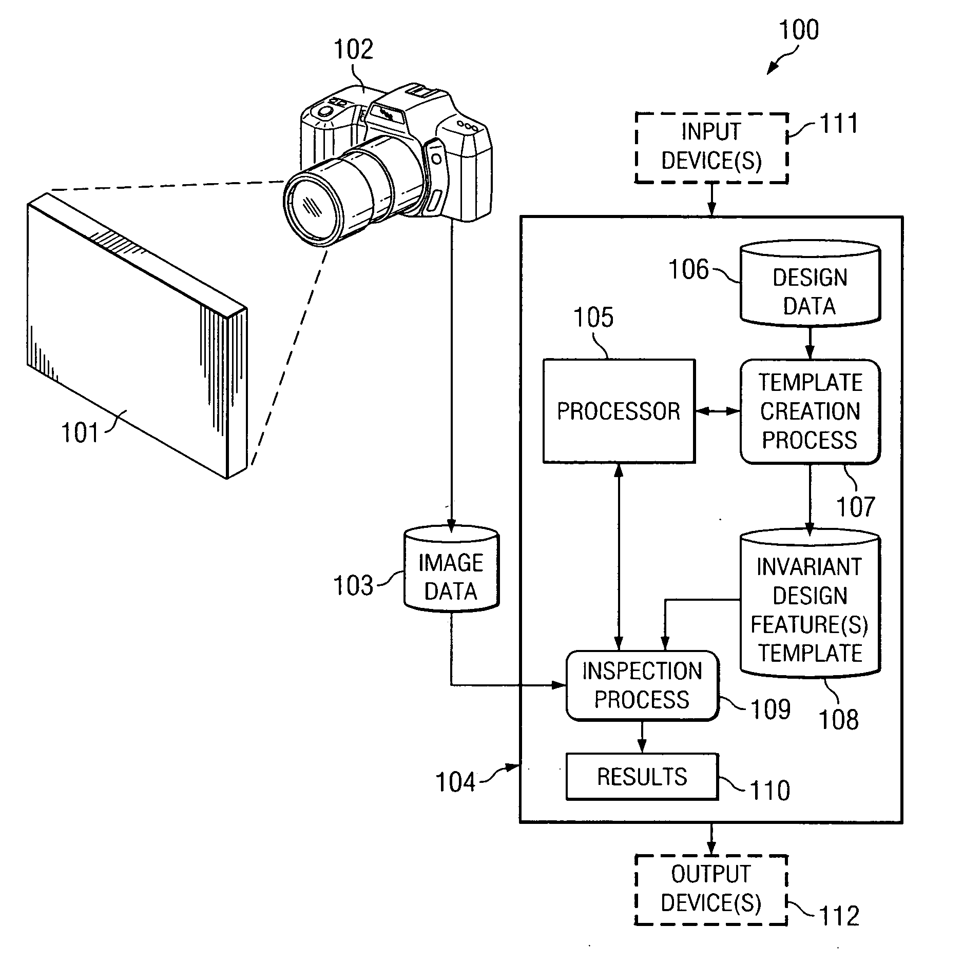
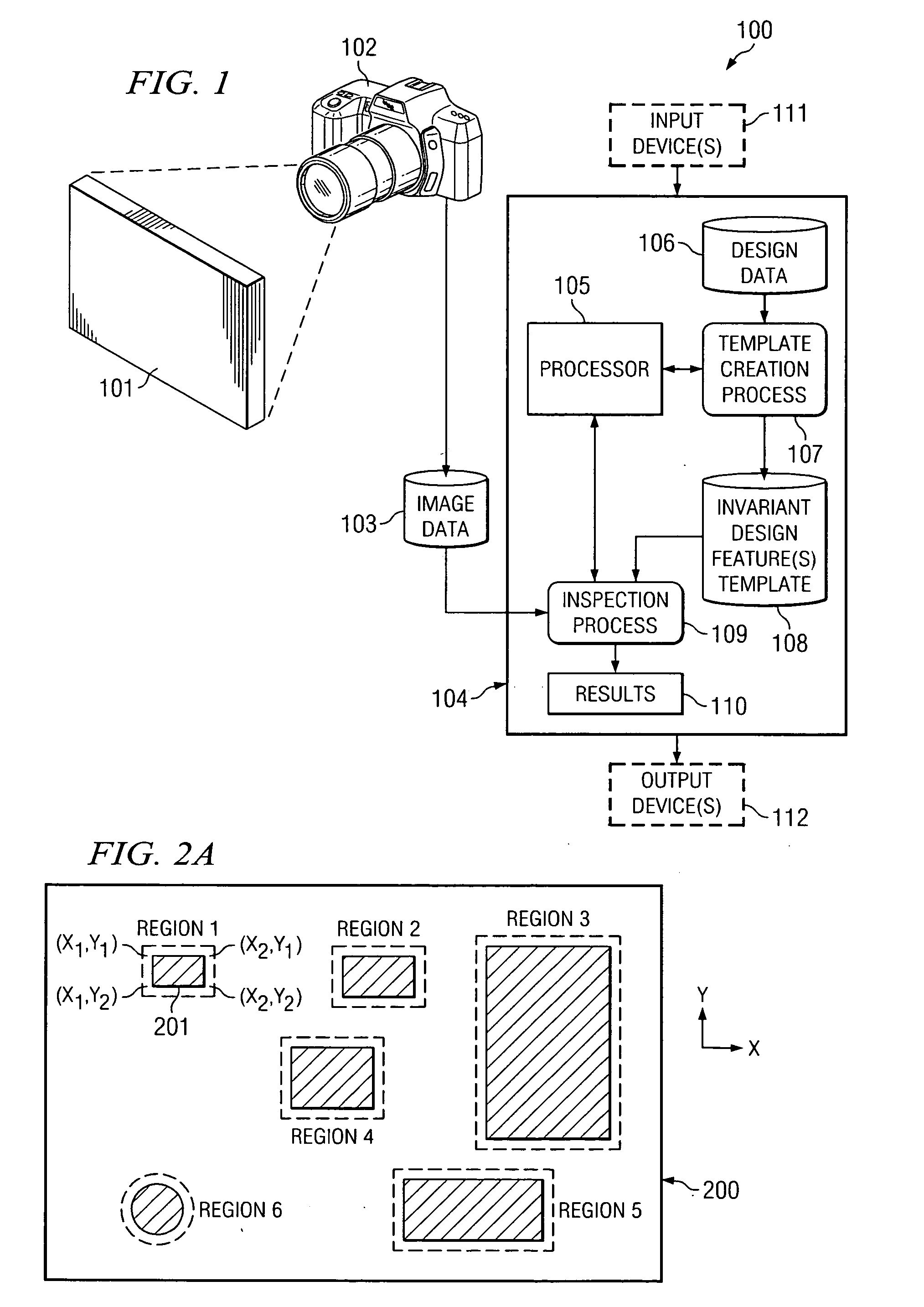
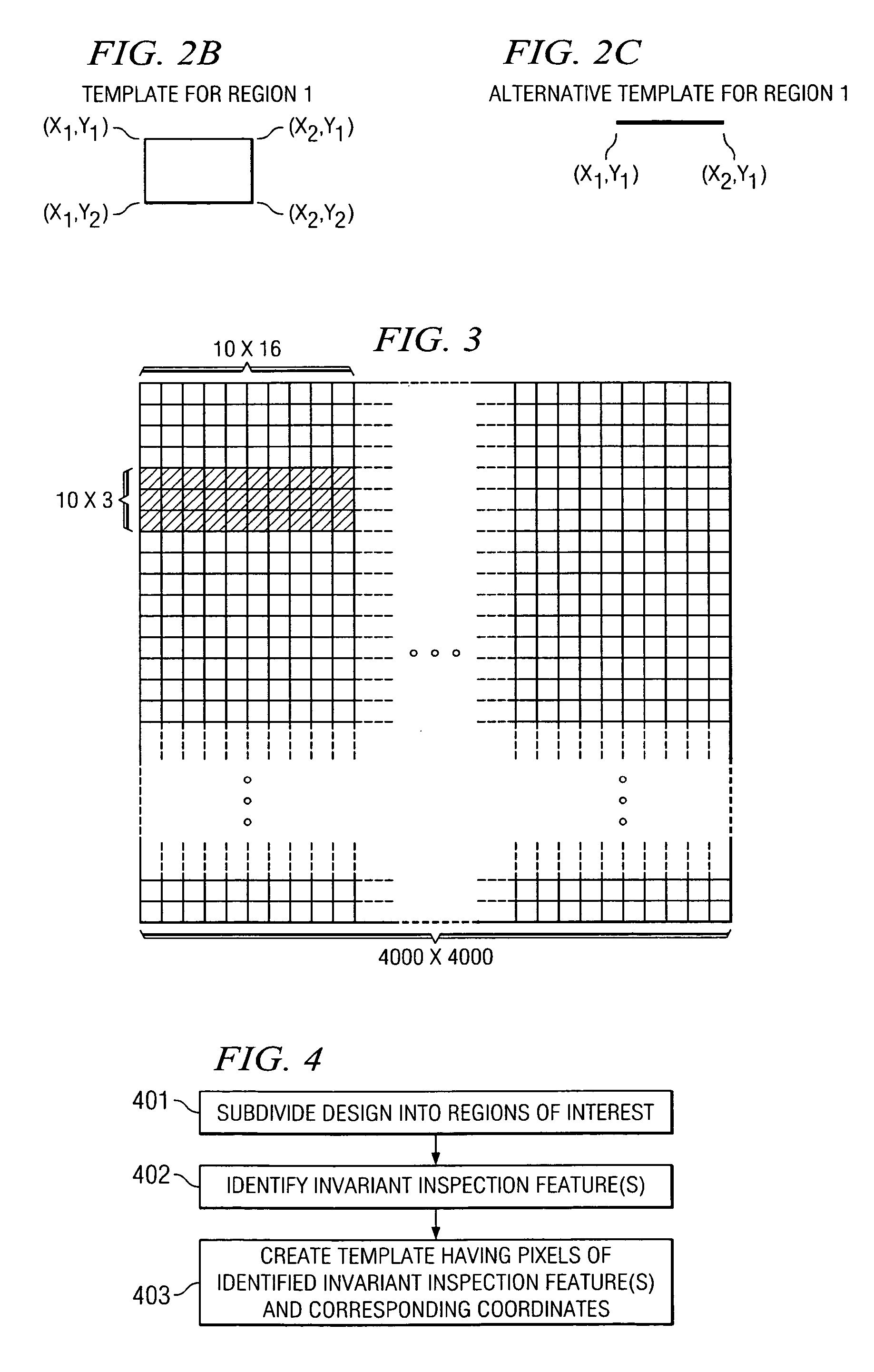
[0017] Certain embodiments are provided for creating a template that includes such invariant feature(s). That is, certain embodiments are provided for determining the invariant feature(s) of a design that are to be used as a template in inspecting objects. Accordingly, a template may comprise information corresponding to at least one pre-selected invariant feature of an
object design. For example, in certain embodiments, a template may be created that includes pixel values for pixels consisting essentially of the invariant feature(s) of a design. The information stored for representing an invariant feature, such as an edge, may include sufficient pixels for accurately defining the edge. For instance, the template may include not only the pixels along the actual edge of a component, but may include some number of pixels on either side of the edge to enable recognition of the edge. For instance, in certain embodiments the template is a shape description of a feature that provides an intrinsic invariance to a specified set of basic transformations, such as shifts in the X-Y plane or monotonic brightness transformations. Accordingly, the amount of pixel values stored in a template may be minimized (e.g., storing the pixel values for only the invariant feature, rather than storing pixel values for a full image or subdivided region thereof). Thus, the amount of storage capacity required for storing the template information may be minimized, and (in many cases more importantly) the efficiency of the inspection process can be improved by reducing the number of pixel comparisons that are made.
[0018] Decreasing the number of selected pixels for the analysis, i.e., selecting only the relevant subset of pixels, provides an additional
advantage to the
decision making process, because it makes the penalty function more sensitive to the important changes in the object under analysis.
[0021] Accordingly, in certain embodiments, different templates for each of various acceptable variations of an object are not needed. Rather, in certain embodiments, a single template may be stored, along with associated penalty values assigned to corresponding types of deviations that may be detected. Thus, in certain embodiments, efficiency is improved in that correlation is performed between an acquired image (of an object under inspection) and the template (e.g., invariant features), and the determined amount of variation in the acquired image with the template (with respect to the invariant features) is used to determine a “penalty.” The determined penalty can then be used to determine whether the object under inspection is acceptable. Accordingly, rather than performing correlation between an image of an object (or a given portion thereof) with a plurality of different templates corresponding to such object's design (or to such given portion thereof) for defining a plurality of acceptable variations in the object, in certain embodiments the correlation need only be performed with one template for each portion of the image that is inspected (e.g., for each component or for certain components that are of interest, etc.), and the results of that correlation are used to determine whether the variations, if any, in the object from the template (e.g., invariant features) are acceptable.
[0022] In accordance with at least one embodiment provided herein,
correlational analysis is performed between defined (template) invariant feature(s) and the corresponding invariant feature(s) of an object under inspection. This approach provides several advantages. First, the pixels corresponding to the selected invariant feature(s) of an object are much fewer than the total pixels of a full image of the object under inspection, and thus performing the correlational analysis using only the invariant feature(s) significantly decreases the number of computations to be performed in the correlational analysis (e.g., typically at least by 10 percent). Additionally, because the analysis is restricted to pre-selected invariant feature(s), greater flexibility is permitted in the object being inspected. For example, a manufacturer may paint its parts a different color than originally expected in the design, and the inspection
system can use the feature(s) that are invariant to such
color changes (e.g., the component edges) for performing the inspection. Thus, changes in characteristics to which the selected inspection features (e.g., selected edges) are invariant, e.g., changes in color, brightness, etc., are permissible without affecting the inspection system's analysis of an object under inspection.

