Constant-velocity joint and image-forming device

a constant speed joint and image-forming technology, applied in the direction of electrographic process apparatus, rotary machine parts, instruments, etc., can solve the problems of low quality of image, warping and low quality of final image, etc., to prevent grease leakage, reduce operating noise of constant speed joint, and eliminate the need for grease

Inactive Publication Date: 2005-12-22
NTN CORP
View PDF7 Cites 87 Cited by
  • Summary
  • Abstract
  • Description
  • Claims
  • Application Information

AI Technical Summary

Benefits of technology

[0020] Since at least one of the outer ring and the cage is formed of a synthetic resin, it is possible to minimize the operating noise of the constant-velocity joint, i.e. the noise produced while torque is being transmitted between the outer ring and the cage. It is also possible to eliminate the need to use grease for lubrication, which in turn eliminates the need for a boot for preventing leakage of grease. This simplifies the structure of the constant-velocity joint.
[0021] The constant-velocity joint can thus be used under practically any circumstances. For example, it can be used in office machines, audio devices, medical devices, household appliances in which it was impossible to use conventional constant-velocity joints. Use of a constant-velocity joint in these devices will greatly increase the freedom of design of these devices, and will also make it possible to reduce the size and cost of the joint.
[0022] The image forming device according to the present invention is characterized in that the shaft of the photoconductor drum and the drive shaft of the drive unit are coupled together through a constant-velocity joint according to the present invention. The constant-velocity joint allows the photoconductor drum to rotate at a constant speed even if the drive shaft of the drive unit and the shaft of the photoconductor drum are inclined relative to each other or otherwise out of alignment with each other.
[0023] This in turn prevents any partial shrinkage and partial expansion of the electrostatic latent image formed by the exposure unit and / or the toner image on the photoconductor drum when transferred on to the transfer material. Thus an extremely high-quality image can be formed.
[0024] The constant-velocity joint according to the present invention needs no lubrication with grease, so that the possibility of the transfer material being soiled with grease is zero, and the maintenance is easy too. The image forming device according to the present invention is produces less operating noise while torque is being transmitted.

Problems solved by technology

Thus, the ultimately obtained image tends to be warped and low in quality.
But since it is extremely difficult to support the drum and mount the motor such that the shaft of the drum and the rotary shaft of the motor exactly align with each other, and instead, the drum shaft and the motor rotary shaft tend to incline relative to each other or otherwise get out of alignment with each other, the photoconductor drum cannot usually be rotated at a constant speed.
The image ultimately obtained thus tends to be low in quality.
But actually, it is difficult to arrange the above two positions exactly diametrically opposite to each other due to assembling errors and / or inclination of the photoconductor drum.
Thus, it will be difficult to completely cancel any shrinkage and expansion of the latent image with the shrinkage and expansion of the toner image.
The ultimately obtained image thus tends to be low in quality.
Thus, while the joint disclosed in this publication is high in strength, it is heavy, needs grease lubrication, and tends to produce large operating noise.
Its use is therefore limited.
For example, it is not suitable for use in office machines, audio devices, medical instruments, household appliances, etc.
If such a constant-velocity joint is used in an image-forming device, grease may leak, thereby soiling the transfer material.
This necessarily increases the number of parts and thus the cost, as well as the size, of the constant-velocity joint.

Method used


Image

  • Constant-velocity joint and image-forming device
  • Constant-velocity joint and image-forming device
  • Constant-velocity joint and image-forming device

Examples


first embodiment

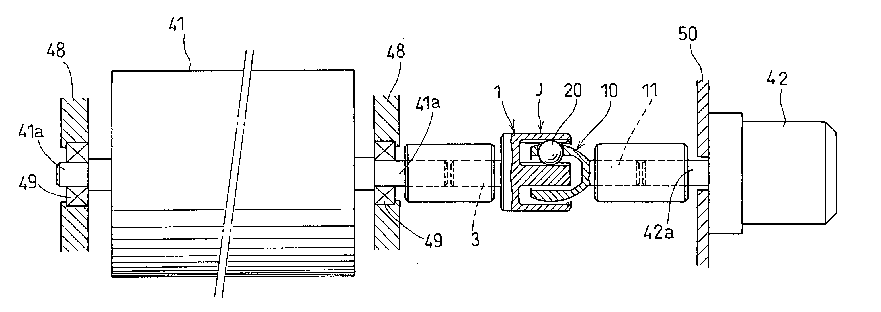
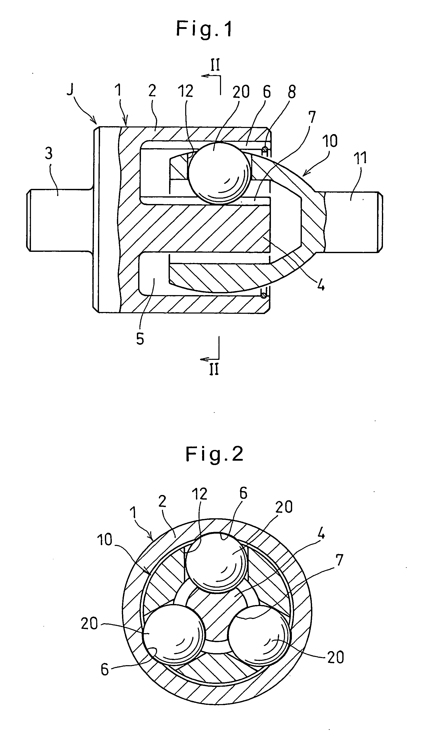
[0033] Now with reference to the drawings, the embodiments of the present invention are described. FIGS. 1 and 2 show the constant-velocity joint according to the present invention. As shown, the constant-velocity joint comprises an outer ring 1, a cage 10 and balls 20.

[0034] The outer ring 1 includes a cup 2 having an opening at one end, and an end wall closing the other end thereof. A first shaft 3 is integrally formed on the outer surface of the end wall of the cup 2. A guide shaft 4 extends from the inner surface of the end wall along the axis of the outer ring 1 to define an annular space between the guide shaft 4 and the cup 2. Three track grooves 6 and three track grooves 7 are formed in the radially inner surface of the cup 2, which defines the radially outer wall of the annular space 5, and in the outer surface of the guide shaft 4, which defines the radially inner wall of the annular space 5, respectively. The track grooves 6 and 7 are circumferentially spaced apart from e...

second embodiment

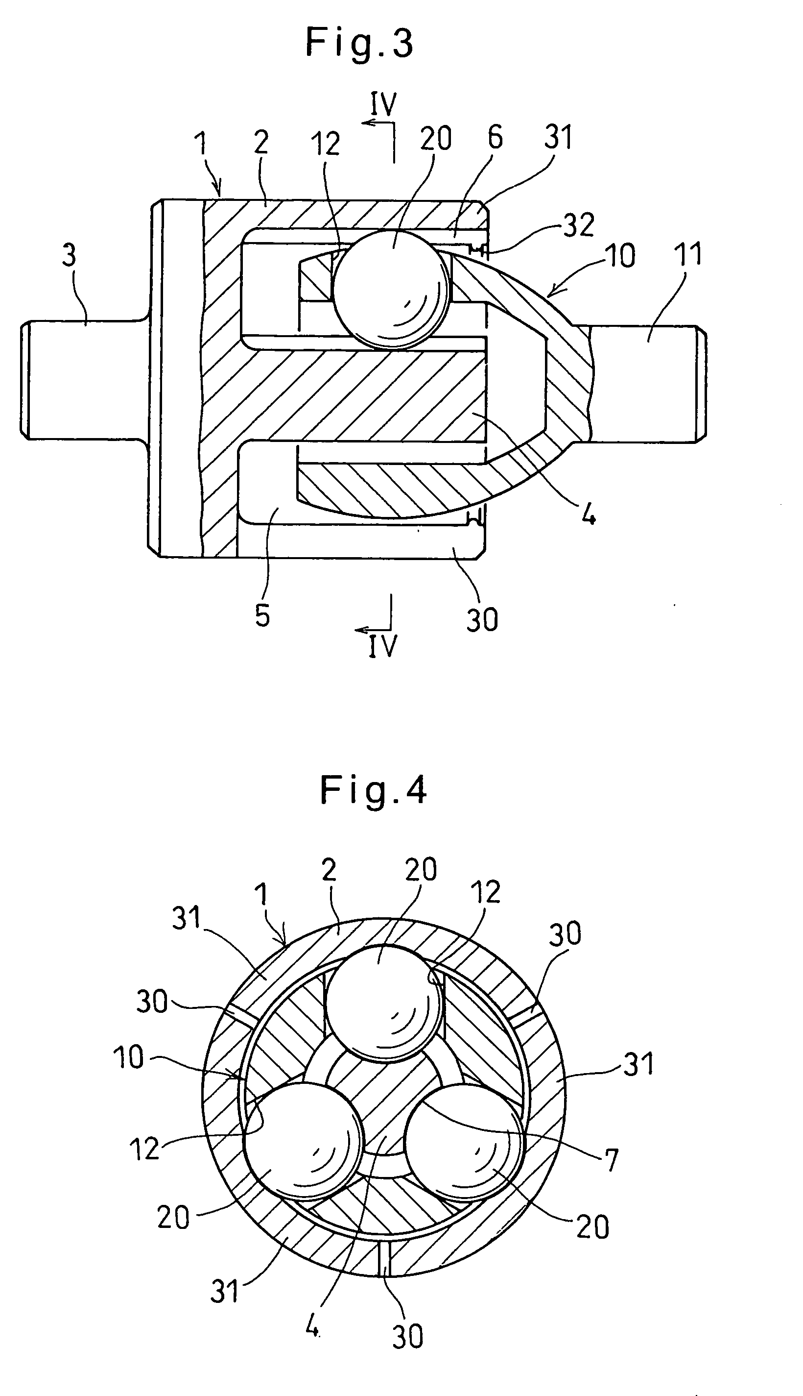
[0060] The constant-velocity joint can thus be easily assembled without using any special tool. No snap ring 8 used in the embodiment of FIG. 1 is necessary, either. The arrangement of the second embodiment thus contributes to a reduction in the number of parts.

[0061] In the second embodiment, if the outer ring 1 is made of a synthetic resin having a high elastic modulus, or if the cup 2 of the outer ring 1 has a sufficient wall thickness, a preload can be applied to the balls 20 from the elastic pieces 31. This allows the constant-velocity joint to operate at a more constant speed with minimum run-out.

[0062] If torque higher than a maximum permissible torque determined by the elastic modulus of the outer ring 1 is applied to the joint, the elastic pieces 31 are allowed to elastically deflect radially outwardly of the cup 2, thereby preventing transmission of torque between the outer ring 1 and the cage 10. The constant-velocity joint thus acts as a torque limiter, too, thereby pre...


PUM


Abstract

A constant-velocity joint includes an outer ring formed with an annular space therein having an opening at one end thereof. The annular space is defined by a radially outer wall and a radially inner wall. One of the radially inner and outer walls is formed with three axially extending track grooves circumferentially spaced apart from each other by 120 degrees. A cage is inserted in the annular space with one end thereof protruding from the opening of the annular space. A second shaft is provided on the one end of the cage. Balls are retained by the cage and adapted to roll in the track grooves. At least one of the outer ring and the cage is formed of a synthetic resin.

Description

BACKGROUND OF THE INVENTION [0001] The present invention relates to a constant-velocity joint through which driving and driven shafts are coupled together so that torque is transmitted from the driving shaft to the driven shaft, and an image forming device using such a constant-velocity joint, such as a copier or a laser beam printer (LBP). [0002] A known image forming device comprises an image-forming unit or units including a photoconductor drum rotated in one direction, and an electrifier, an exposure unit, a developing unit and a transfer / electrifier that are arranged around the radially outer surface of the photoconductor drum. The electrifier uniformly electrostatically charges the entire radially outer surface of the drum. The light exposure unit then emits image-forming light based on image information onto the drum to form an electrostatic latent image on the drum. The developing unit supplies toner onto the latent image to form a toner image. The toner image is transferred...

Claims


Application Information

Patent Timeline
Patent Type & Authority Applications(United States)
IPC IPC(8): G03G15/00
CPCG03G15/757Y10S464/903F16D3/221
Inventor OHASHI, MASAAKIFUKUZAWA, SATORU
Owner NTN CORP
Why Eureka
Try Eureka