Disposable bioreactor/fermenter

a bioreactor and fermenter technology, applied in the field of biopharmaceutical industry, can solve the problems of static systems, inconvenient reconfiguration, and inability to meet the needs of customers,

Inactive Publication Date: 2005-12-22
MILLIPORE CORP
View PDF15 Cites 63 Cited by
  • Summary
  • Abstract
  • Description
  • Claims
  • Application Information

AI Technical Summary

Benefits of technology

[0017] The present invention is a bioreactor or fermenter formed of a container having two or more walled. One or more inlets and one or more outlets are formed in one or more of the walls of the container. At least one of the one or more inlets is formed in the bottom wall of the container and used for the introduction of one or more gases. A gas distribution device is formed within the body of the container adjacent the bottom gas inlet and a hydrophobic filter is mounted to the bottom wall gas inlet, upstream of the gas inlet. The distribution device is formed such as by bonding the two facing wall surfaces of the container together at discrete and spaced apart locations to form a series of gas ports into the remainder of the container. The hydrophobic filter acts to purify the gas entering the container so as to prevent the introduction of contaminants such as microbes into the container. It also acts as a valve, preventing liquid in the bag from passing through its hydrophobic structure thus preventing any back flow when positive pressure from the gas supply is not being imposed upon the bag.
[0019] In another embodiment, the bottom wall of the container has an upward taper, either to one side or both sides or a rounded bottom wall to eliminate any deadspace in corners.

Problems solved by technology

The cost of such a system is often prohibitive.
Moreover, such systems are static, often being welded together and not easily reconfigured.
Additionally, the initial capital cost is several times less than that of stainless steel allowing one to manufacture biopharmaceuticals in smaller amounts, making available new therapeutic agents that prior to this advancement were not economically justified and allowing for the expansion of contract manufacturing of such products or when demand requires additional capacity quickly.
Such a system requires the use of capital-intensive equipment, with components that are susceptible to wear.
Additionally, the size of the bag that can be used with the table is limited by the size of table and the lifting capability of its motors / hydraulics.
Additionally, due to weight considerations, the bag size and volume is restricted by the lifting capacity of the equipment and the strength of the bag.
Both have the potential for leakage of the liquid in the container which can potentially contaminate the contents of the bag of the upstream components of the system such as the gas supply system.

Method used


Image

  • Disposable bioreactor/fermenter
  • Disposable bioreactor/fermenter
  • Disposable bioreactor/fermenter

Examples


Embodiment Construction

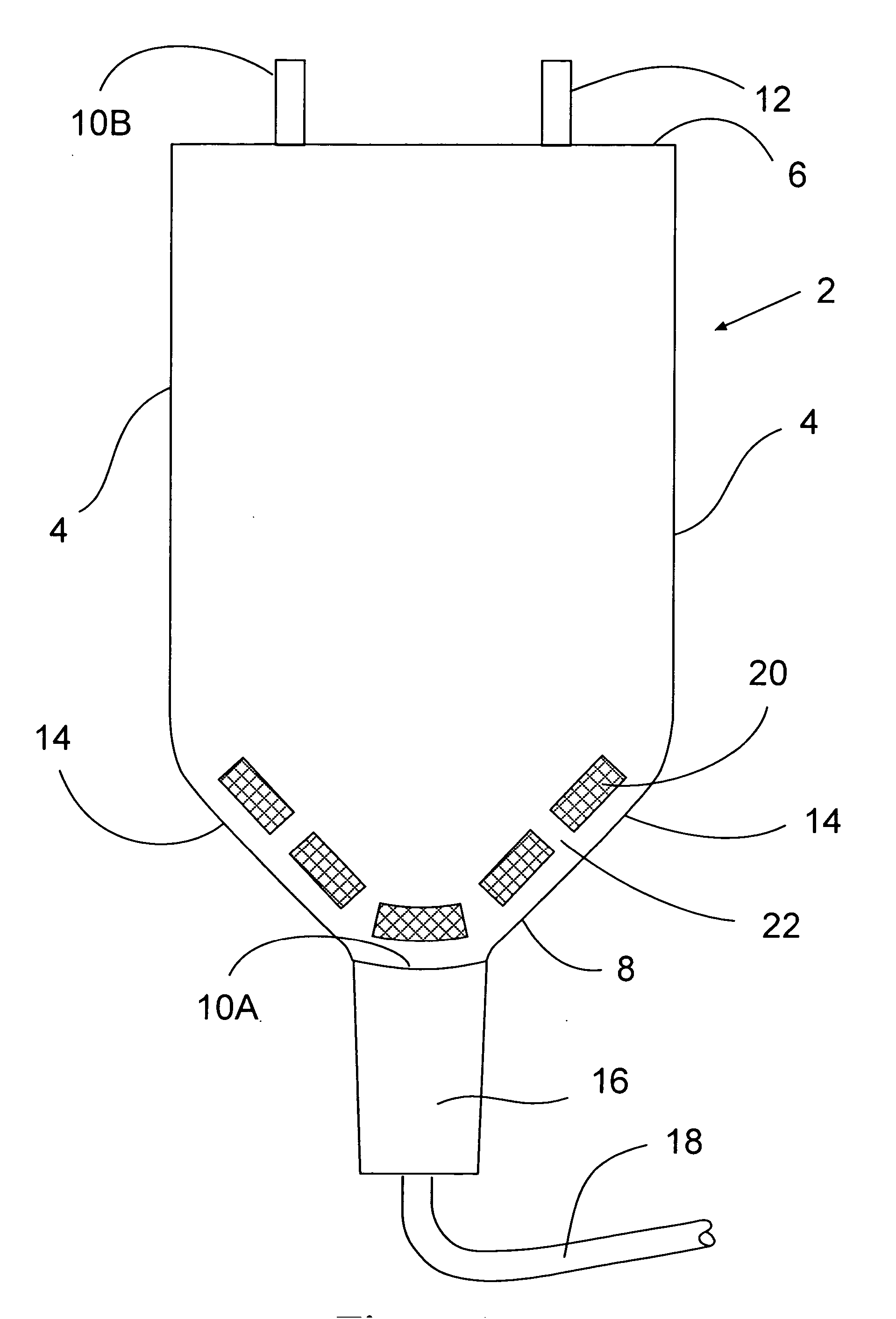
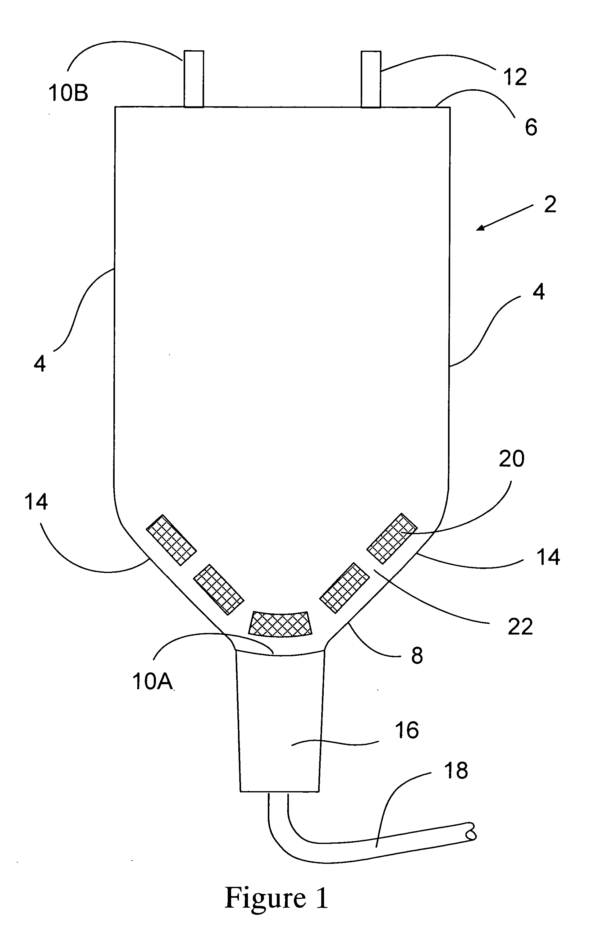
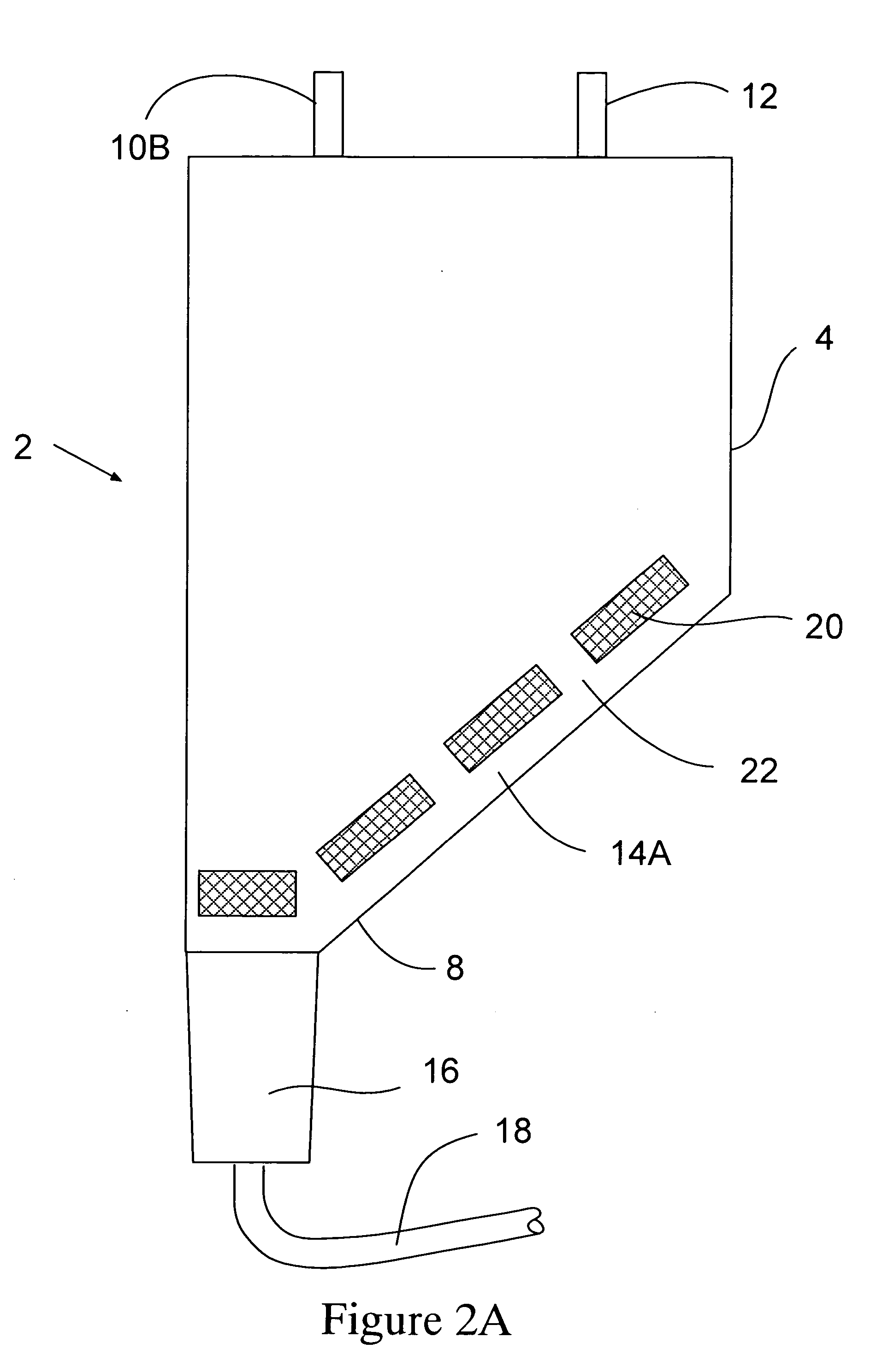
[0029] The present invention relates to a disposable fermenter or bioreactor. FIG. 1 shows a first embodiment of the present invention. As shown the device is comprised of a bag 2 having two substantially vertical sidewalls 4, a top wall 6 and a bottom wall 8. One or more inlets 10A-B and one or more outlets 12 are formed one or more walls of the in the bag 2. One inlet for gas 10A is located at the lowermost portion of the bottom wall 8 of the container 2. Attached to the inlet 10A and upstream of the inlet 10A is a hydrophobic filter 16. Connected to the other end of the filter 16 is a gas line 18 for supplying air and / or other gases to the container 2. A series of one or more gas distribution devices 20 are formed in the container adjacent the bottom wall 8. The one or more devices are designed to allow gas to enter the container adjacent the inlet 10A. The devices form one or more gas ports 22 which distribute the gas through out the container before it enters the remainder of t...


PUM

PropertyMeasurementUnit
pore sizeaaaaaaaaaa
pressureaaaaaaaaaa
flexibleaaaaaaaaaa

Abstract

The present invention is a bioreactor or fermenter formed of a container having two or more walled. One or more inlets and one or more outlets are formed in one or more of the walls of the container. At least one of the one or more inlets is formed in the bottom wall of the container and used for the introduction of one or more gases. A gas distribution device is formed within the body of the container adjacent the bottom gas inlet and a hydrophobic filter is mounted to the bottom wall gas inlet, upstream of the gas inlet. The distribution device is formed such as by bonding the two facing wall surfaces of the container together at discrete and spaced apart locations to form a series of gas ports into the remainder of the container. The hydrophobic filter acts to purify the gas entering the container so as to prevent the introduction of contaminants such as microbes into the container. It also acts as a valve, preventing liquid in the bag from passing through its hydrophobic structure thus preventing any back flow when positive pressure from the gas supply is not being imposed upon the bag.

Description

CROSS REFERENCE RELATED APPLICATIONS [0001] This application claims the benefit of U.S. Provisional Application No. 60 / 576,326, filed on Jun. 2, 2004.BACKGROUND OF THE INVENTION [0002] The biopharmaceutical industry has traditionally used stainless steel systems and piping in their manufacturing process as they are capable of being steam sterilized and reused. [0003] The cost of such a system is often prohibitive. Moreover, such systems are static, often being welded together and not easily reconfigured. [0004] The industry has begun to explore an alternative approach, namely to use plastic, single disposable bags and tubing to replace the traditional stainless steel. This allows one the flexibility to rearrange these systems at minimal cost. Additionally, the initial capital cost is several times less than that of stainless steel allowing one to manufacture biopharmaceuticals in smaller amounts, making available new therapeutic agents that prior to this advancement were not economi...

Claims


Application Information

Patent Timeline
Patent Type & Authority Applications(United States)
IPC IPC(8): B01D69/02B65D35/28C12M1/00C12M1/04C12M1/09C12M3/00
CPCC12M23/02C12M29/06C12M23/14
Inventor PROULX, STEPHEN
Owner MILLIPORE CORP
Why Eureka
Try Eureka