System for delivering a diluted solution

Inactive Publication Date: 2005-12-22
THE GENERAL HOSPITAL CORP +2
View PDF37 Cites 106 Cited by
  • Summary
  • Abstract
  • Description
  • Claims
  • Application Information

AI Technical Summary

Benefits of technology

[0007] The invention also features an alternative method for delivering analytes to an analytical device including providing a sample container having an outlet and containing a fluid medium including the analytes; the analytical device; a fluidic switch; and a diluent reservoir containing diluent, wherein the outlet is fluidically connected to the analytical device, and the fluidic switch is fluidically connected to the analytical device and the diluent reservoir; pumping the diluent through the fluidic switch and the analytical device into the sample container to dilute the sample, wherein the fluidic switch directs the diluent into the analytical device; and pumping at least a portion of the diluted sample through the outlet and into the analytical device, during which the diluted sample in the sample container is agitated to substantially maintain homogeneity. In this method, the diluted sample may be pumped through the analytical device, e.g., in its entirety. The fluidic switch may prevent the diluted sample from entering the diluent reservoir, e.g., by directing the sample that has passed through the analytical device to a waster container.
[0012] Another delivery system of the invention includes an analytical device capable of being fluidically connected to a sample container; a fluidic switch; a diluent reservoir; and an agitator capable of substantially maintaining homogeneity in a fluid medium, wherein the fluidic switch is fluidically connected to the analytical device and the diluent reservoir, and wherein the fluidic switch is capable of preventing the flow of fluid between the analytical device and the diluent reservoir.
[0016] The systems and plugs of the invention may be employed in the methods described herein. In addition, the wetting methods described herein may be used to enhance the introduction of fluid media in the methods and systems of the invention.
[0023] By “specifically binding” a type of analyte is meant binding analytes of that type by a specified mechanism, e.g., antibody-antigen interaction, ligand-receptor interaction, nucleic acid complementarity, protein-protein interaction, charge-charge interaction, and hydrophobic-hydrophobic or hydrophilic-hydrophilic interactions. The strength of the bond is generally enough to prevent detachment by the flow of fluid present when analytes are bound, although individual analytes may occasionally detach under normal operating conditions.

Problems solved by technology

It is however difficult to transfer cells from such containers to analytical devices in an automated way.
For example, blood cells may sediment potentially leading to inaccurate blood counts.
In addition, the transfer of blood and subsequent mixing with reagents or diluents may lead to cell loss, sample contamination from the environment, or risk of infection to personnel.

Method used


Image

  • System for delivering a diluted solution
  • System for delivering a diluted solution
  • System for delivering a diluted solution

Examples


example 1

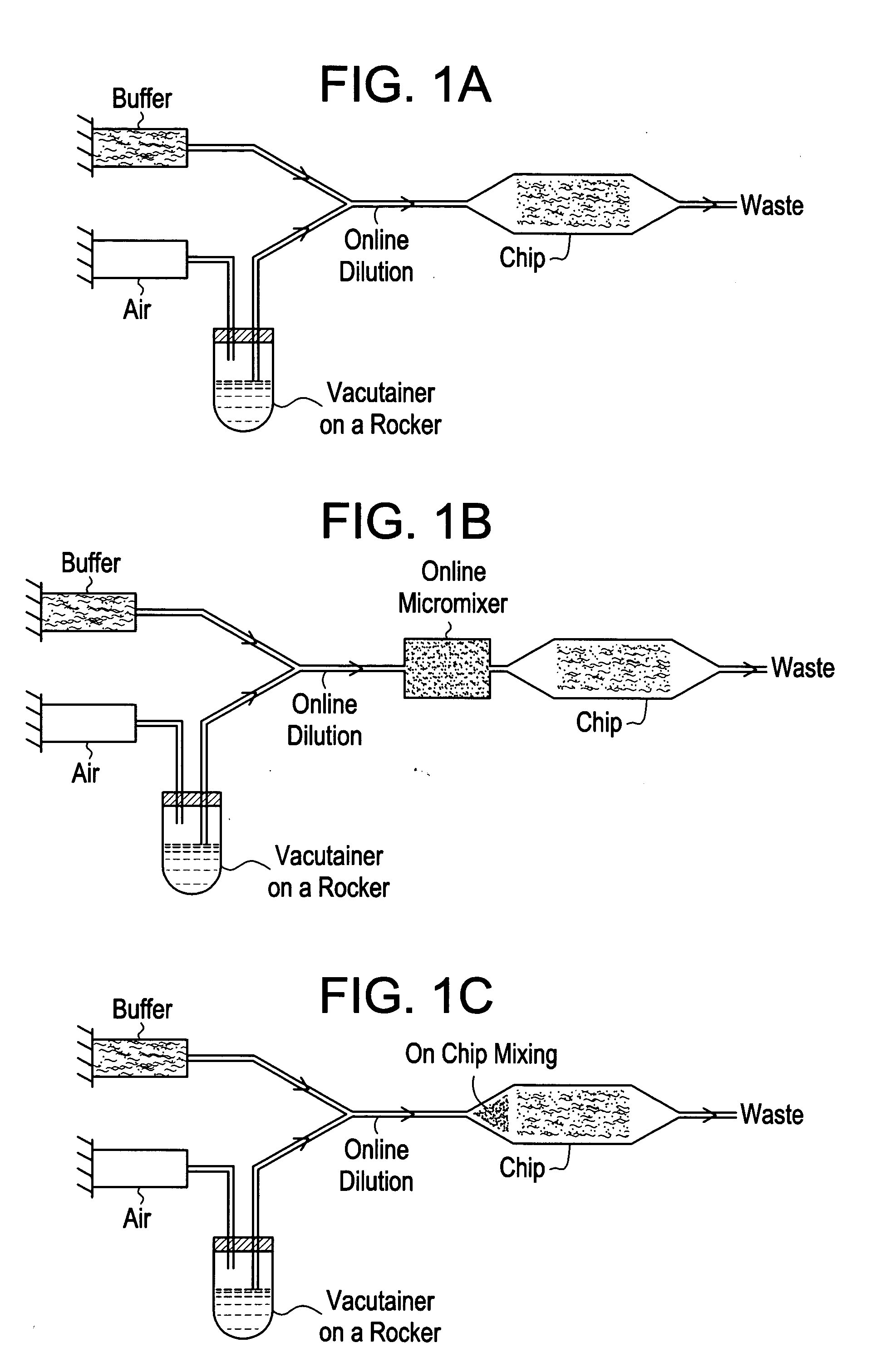
[0037] This system is described with reference to FIGS. 1a-1c. The system is based on positive displacement of blood from a sample container with inline dilution, control of sedimentation, and optional enhancement of mixing. A positive displacement pump, e.g., a syringe pump, drives a pressurizing fluid, such as air or immiscible oil, into the sample container through an inlet, e.g., a needle penetrating a septum. This influx of fluid displaces blood through an outlet, e.g., a second needle penetrating the septum (FIG. 1a). In order to enable extraction of the majority of the blood sample from the sample container, the outlet is preferably long enough to reach the bottom of the tube. Sedimentation is prevented by mechanically rocking the container through an angle of slightly less than 180°, such that the tip of the inlet does not contact the blood. This arrangement avoids entrainment of pressurizing fluid in the blood to be delivered to an analytical device. Diluent may be supplied...

example 2

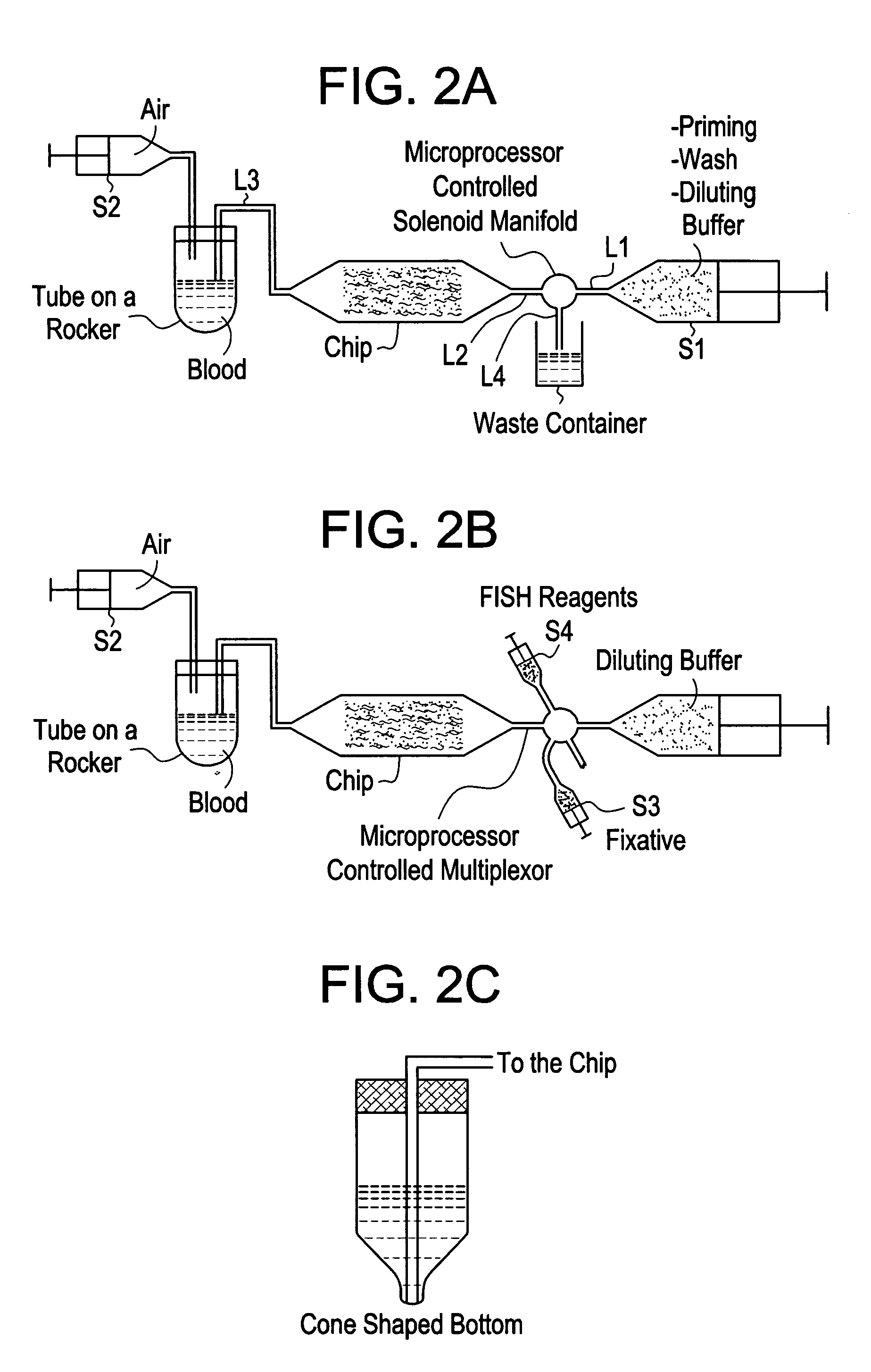
[0038] The system is based on the serial fluidic connection of a blood container, an analytical device, and a diluent reservoir. The system makes use of both inlet and outlet connections to the analytical device to enable priming or wetting of the device while diluting the blood sample to any desired volume. FIG. 2a is a schematic representation of the system. The system is operated as follows: a mechanical rocker holds a blood sample in the sample container, diluent from the reservoir is pushed by a positive displacement pump (S1) into the sample container through line L1, a fluidic switch, e.g., a microprocessor controlled solenoid manifold, actuated to block flow to L4, L2, the analytical device, e.g., a microfluidic device, and L3 at a chosen flow rate to enable priming of the device and timely dilution of the blood. The flow rates may range from 0.1-200 ml / hr. Once the blood is diluted to the desired volume, the pumping of S1 is terminated, the diluted blood sample is then pump...

example 3

[0039] With reference to FIG. 3, another embodiment of the device disposes the blood in a sample container, e.g., a syringe, S2 and the diluent in another container, e.g., a second syringe, S1. S1 is connected to one port of an analytical device, and S2 is connected to another port of the device. Diluent is pumped through the device by displacement, e.g., a combination of push and pull of syringes. The diluent primes the device and dilutes the blood in S2. S2 may be in constant rotation to aid in mixing of the blood and buffer and to prevent cell sedimentation in the container during processing. A coupler may be employed to prevent rotation induced twisting of the fluid line connecting S2 to the device. At least a portion of the diluted blood sample is then passed through the device and into S1.


PUM


Abstract

The invention features methods and devices for the delivery of a fluid medium containing analytes, e.g., particles, solutes, or solvents, to an analytical device. The systems are designed to minimize contact with potentially hazardous, fragile, or valuable samples. The systems allow for the dilution, mixing, and introduction of the fluid medium to an analytical device, followed by possible further analysis or sample manipulation.

Description

CROSS-REFERENCE TO RELATED APPLICATIONS [0001] This application claims benefit of U.S. Provisional Application No. 60 / 549,680, filed Mar. 3, 2004, which is hereby incorporated by reference.BACKGROUND OF THE INVENTION [0002] The invention relates to the field of sample delivery and microfluidics. [0003] Blood samples are routinely drawn for diagnostic purposes in standardized glass collection tubes containing anticoagulants such as EDTA, citrate, or heparin. The Vacutainer brand (e.g., from Becton Dickinson) of tubes facilitates drawing of patient blood samples by virtue of a partial vacuum in the tube, which is retained during storage of the tubes by a silicone rubber stopper / septum. It is however difficult to transfer cells from such containers to analytical devices in an automated way. For example, blood cells may sediment potentially leading to inaccurate blood counts. In addition, the transfer of blood and subsequent mixing with reagents or diluents may lead to cell loss, sample...

Claims


Application Information

Patent Timeline
IPC IPC(8): B01L3/00B01L3/14G01N1/10G01N1/14G01N1/38G01N35/10
CPCB01L3/5027B01L3/50825B01L2200/026Y10T436/2575G01N1/38G01N35/1095G01N1/14
Inventor COSMAN, MAURY D.KAPUR, RAVICARVALHO, BRUCE L.BARBER, TOMBALIS, ULYSSES J.TONER, MEHMETHUANG, LOTIEN R.GRAY, DARREN S.
Owner THE GENERAL HOSPITAL CORP
Why Eureka
Try Eureka