Log splitter

a technology of log splitter and splitter body, which is applied in the field of log splitter, can solve the problems of hydraulic fluid not flowing properly between the reservoir, valve, pump and cylinder, and the size and weight of the conventional and available splitter is too large and too heavy for highway use, etc., to achieve the effect of maximizing the mixing of hydraulic fluid, minimizing the direct flow of fluid, and reducing the weigh

Inactive Publication Date: 2005-12-29
BRAVE PRODS
View PDF12 Cites 16 Cited by
  • Summary
  • Abstract
  • Description
  • Claims
  • Application Information

AI Technical Summary

Benefits of technology

[0013] There is provided a splitter which is smaller and lighter in weight than conventional splitters so as to meet the uses described above. The splitter includes an elongated frame, a wedge at one end of the frame and a hydraulic cylinder and piston / ram at the other end of the frame. The piston / ram is movable toward and away from the wedge. A hydraulic fluid reservoir with an inlet and an outlet is provided in association with the frame and includes an elongated tube within the reservoir for maximizing the mixing of hydraulic fluid entering the reservoir with fluid therein and minimizes the direct flow of fluid between the inlet to the outlet. The log splitter of this invention is constructed so as to enhance proper hydraulic fluid flow between the reservoir and cylinder even when the splitter is not level or in a tipped position.

Problems solved by technology

However, it has been found that available log splitters are not suitable for highway use since they are not towable at highway speeds.
Moreover, such log splitters present problems when the vehicle is backed up, particularly as it can't be seen due to its short width.
Conventional and available splitters are too large and too heavy for such uses and / or shipment.
When the splitter is not level, or in a tipped position, the hydraulic fluid may not flow properly between the reservoir, valve, pump and cylinder.

Method used


Image

  • Log splitter
  • Log splitter
  • Log splitter

Examples


Embodiment Construction

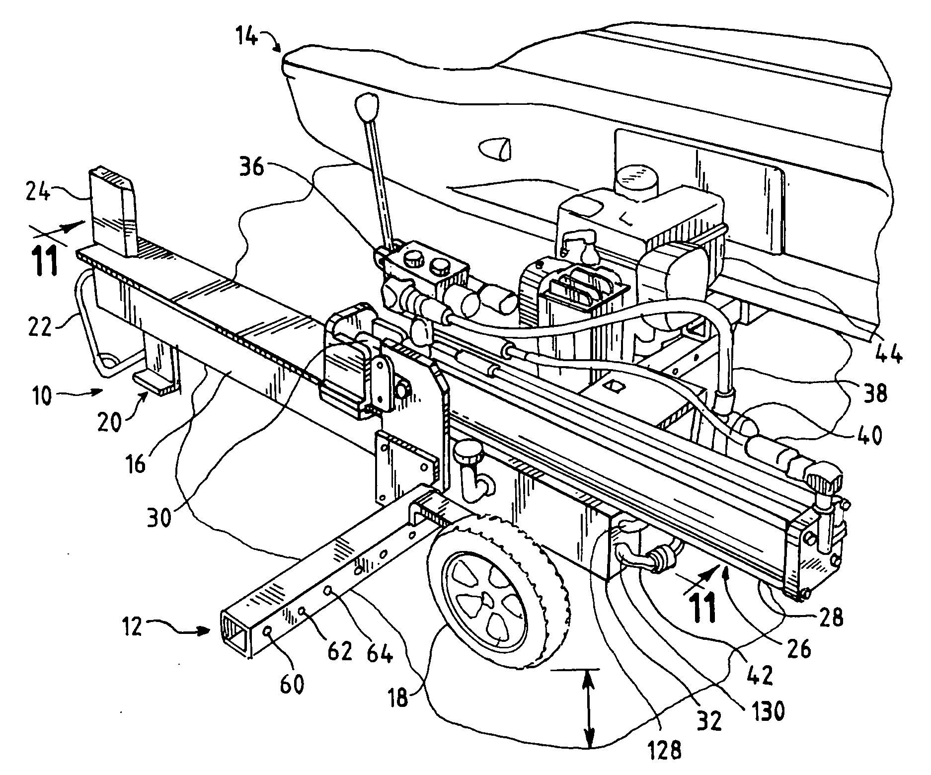
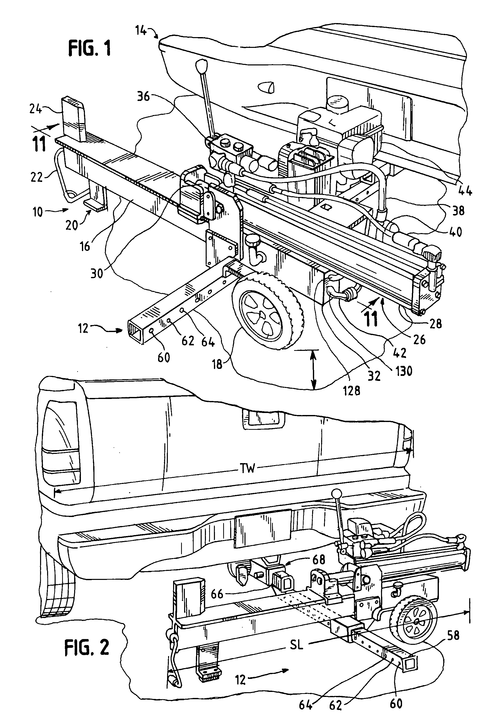
[0039] Referring now to the drawings and figures such as FIGS. 1 and 7, there is seen a log splitter 10 generally that is mounted to and carried by a support arm 12 generally which is mounted to the back of a vehicle 14 generally and above the road surface.

[0040] The splitter 10 generally includes an elongated frame 16 which includes a pair of wheels, such as 18, mounted to the underside and at one end of the frame. An arm or stop bracket 20 is also on the underside of the frame at the other end. A lifting handle 22 is secured to the frame adjacent the arm or stop bracket 20 so as to permit the splitter to be lifted and rolled to a destination, like the mounting position or a position for use off the support arm.

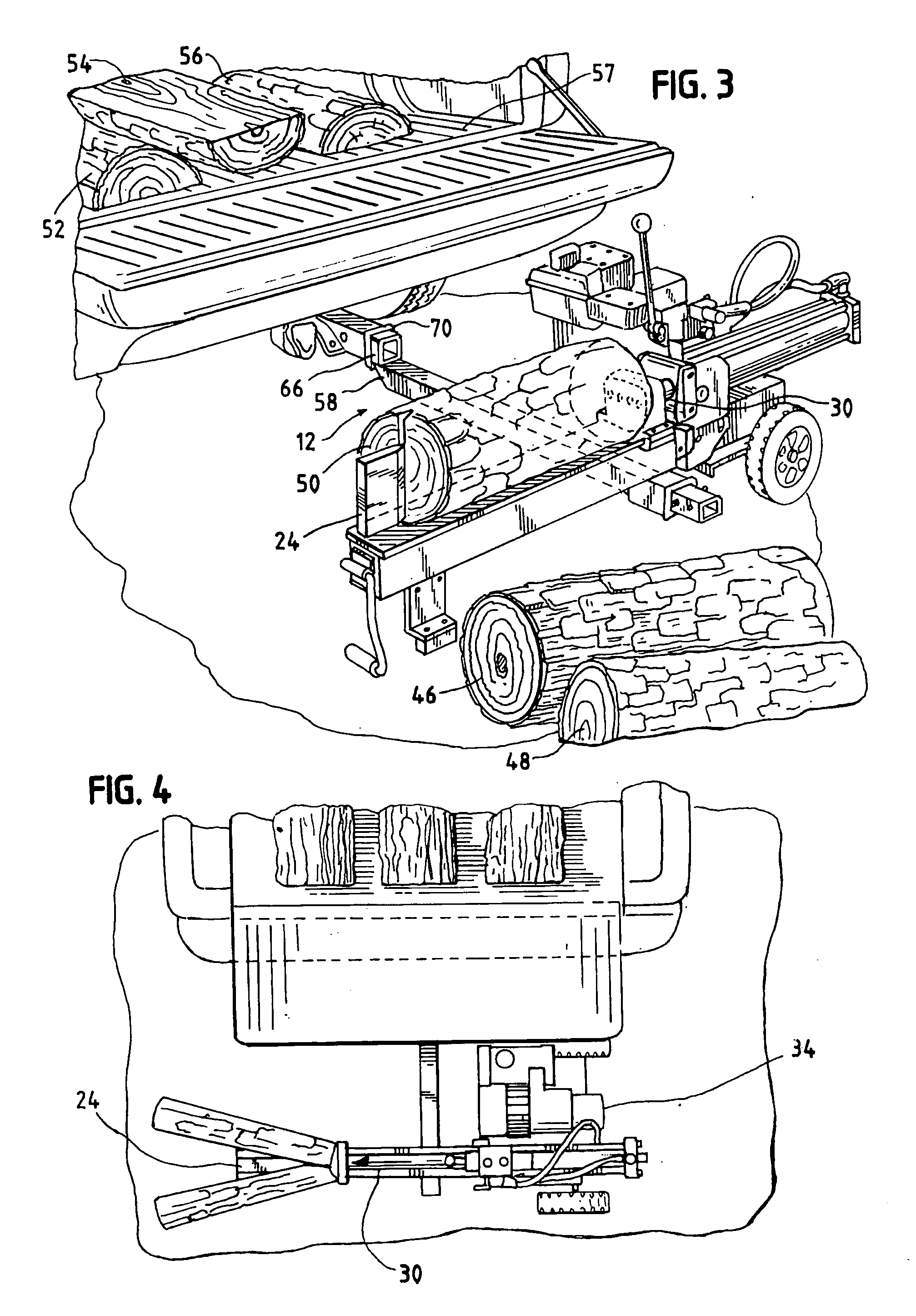
[0041] A log splitting wedge 24 is mounted to the top side of the frame at one end and generally above the stop bracket. A hydraulic cylinder assembly 26 is mounted at the other end of the frame above the wheels, such as 18. The cylinder assembly includes a cylinder 28, a ...


PUM


Abstract

A log splitter which includes an elongated frame which defines a reservoir for hydraulic fluid. A log splitting wedge secured to one end of the frame and a hydraulic cylinder and ram/piston secured to the other end of the frame. The ram/piston being movable toward and away from the wedge. The reservoir includes an inlet and outlet and a discharge tube associated with the inlet having a length effective to discharge incoming fluid into the reservoir at a position remote from the inlet. The elongated tube may be associated with the reservoir outlet so as to draw fluid from the reservoir and thus maximize flow from the reservoir even if the reservoir, or log splitter is in a tipped position. A log splitter and arm for mounting the splitter to a vehicle having a hitch style receiver secured to the rear of the vehicle. The splitter has a substantially linear working action. The mounting system includes an elongated arm for securement to the receiver in a cantilever fashion. The splitter is adapted to be secured, by a pin or a set screw mechanism, to the arm and be supported above the ground. The splitter's linear working action is substantially normal to the vehicle's direction of movement and the support arm. This system permits the vehicle to travel at normal highway speeds and carry the splitter.

Description

CROSS REFERENCE TO RELATED APPLICATION [0001] This application is a continuation-in-part of application Ser. No. 10 / 876,326 filed Jun. 24, 2004.FIELD OF THE INVENTION [0002] This invention relates to log splitters and more particularly to a log splitter which is smaller and lighter in weight than available conventional splitters and that can be mounted to and carried on a vehicle on a road or highway. BACKGROUND OF THE INVENTION [0003] Wood in the form of logs is frequently used as a fuel in stoves, fireplaces, furnaces and at remote locations such as campsites. The log must be of a size suitable for use. Usually this means that the log is to be cut and split to size. Such sizing can be by a hydraulic log splitter wherein a hydraulic ram drives the log against a wedge which splits or cuts the log. [0004] Frequently the source of wood or logs is in a remote location, such as a forest. Thus, it is necessary to bring the log splitter to the location. In addition, the site where the woo...

Claims


Application Information

Patent Timeline
Patent Type & Authority Applications(United States)
IPC IPC(8): B27L7/00B27L7/08
CPCB27L7/00
Inventor WALKER, THOMAS MICHAELWALKER, CHRISTOPHER GERARD
Owner BRAVE PRODS
Why Eureka
Try Eureka