
Time of flight mass analyzer having improved detector arrangement and method of operating same

a mass analyzer and detector arrangement technology, applied in the field of mass analyzers, can solve the problems of difficult to distinguish compounds of similar m/z, large and expensive time-of-flight instruments, and difficult to analyze, and achieve the effect of improving the arrangement of ion detectors

Inactive Publication Date: 2005-12-29
BECKMAN COULTER INC
View PDF25 Cites 16 Cited by
  • Summary
  • Abstract
  • Description
  • Claims
  • Application Information

AI Technical Summary

Problems solved by technology

Although time-of-flight instruments are usually large and expensive due to the nature of the technique, the analysis times are typically short because there is no need to scan through an m / z range to get results.
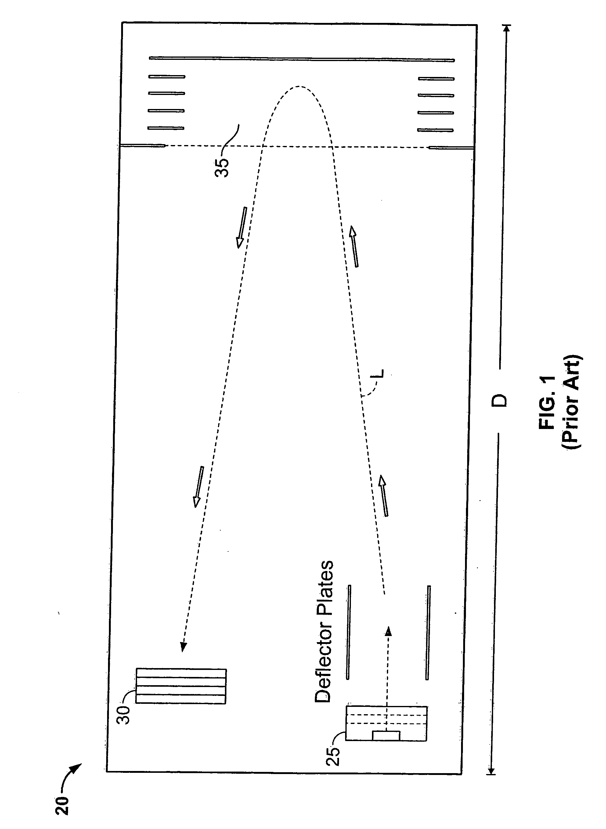
Because the flight time of the ions along the flight path is short, especially with reasonably sized instruments, compounds of similar m / z are difficult to distinguish and, as such, relatively low resolutions on the order of only several hundreds are typical of these instruments.
Thus, development trends with respect to time-of-flight mass spectrometers have gone in the direction of large, increasingly complex designs requiring highly specialized components and tight manufacturing tolerances.

Method used


Image

  • Time of flight mass analyzer having improved detector arrangement and method of operating same
  • Time of flight mass analyzer having improved detector arrangement and method of operating same
  • Time of flight mass analyzer having improved detector arrangement and method of operating same

Examples


Embodiment Construction

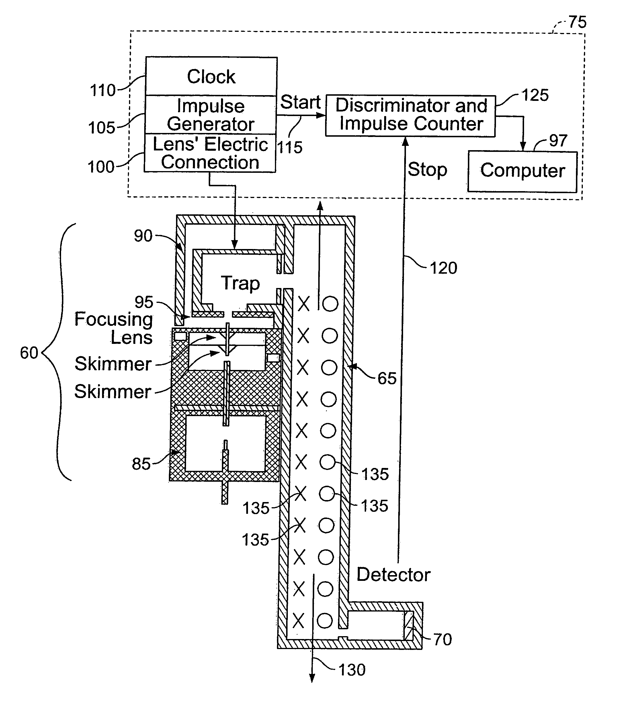
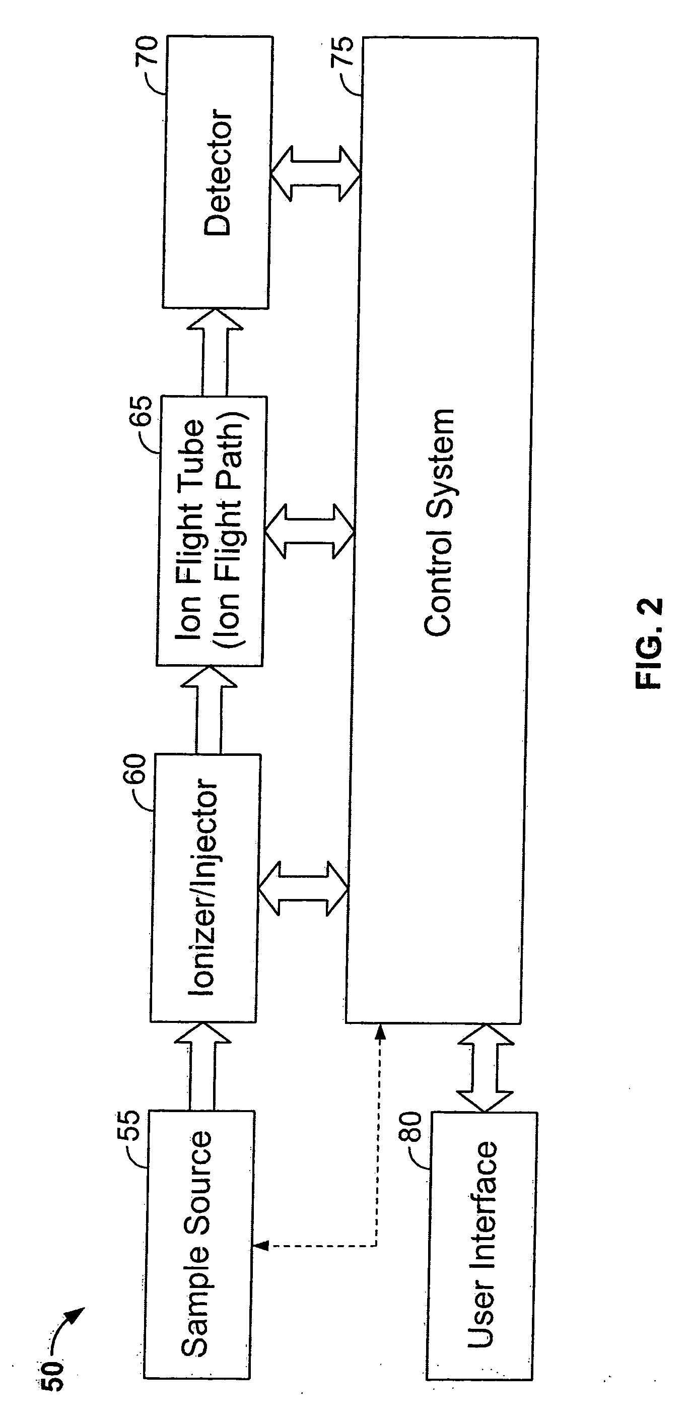
[0019] The basic components of a time-of-flight mass analyzer constructed in accordance with one embodiment of the invention are shown in FIG. 2 in block diagram form. As illustrated, the analyzer 50 includes a sample source unit 55, an ionizer / ion injector 60, an ion flight path that includes ion flight tube 65, and an ion detector 70. Although the term “tube” has been used in connection with schematic block 65, the use of the term has been undertaken for the sake of simplicity and is not meant to constrain the corresponding structure to a particular shape. Rather, the term is intended to encompass all of the various element shapes that can be used to constrain ions to a flight path of the type set forth below.

[0020] The components of the mass analyzer 50 may be automated by one or more programmable control systems 75. To this end, control system 75 may be used to execute one or more of the following automation tasks:

[0021] a) control of the ionization and ion injection parameter...


PUM

PropertyMeasurementUnit
flight timeaaaaaaaaaa
frequencyaaaaaaaaaa
lengthaaaaaaaaaa

Abstract

A time-of-flight mass analyzer having an improved ion detector arrangement is disclosed. The analyzer includes an ionizer that generates the ions that are to be analyzed. A flight tube accepts the ions provided from the ionizer and constrains the ions to a generally helical ion flight path using a generally static electric field. An ion detector is disposed in the flight tube to intercept ions as the ions travel along the substantially helical ion flight path. At least one timer is provided to determine the flight times of the ions along an ion path that comprises at least the generally helical ion path. The timer is responsive to the impingement of ions on the ion detector.

Description

CROSS-REFERENCE TO RELATED APPLICATIONS [0001] The present application is a continuation-in-part of U.S. Ser. No. 10 / 692,301, filed Oct. 23, 2003, and entitled “TIME OF FLIGHT MASS ANALYZER HAVING IMPROVED MASS RESOLUTION AND METHOD OF OPERATING SAME”.FIELD OF THE INVENTION [0002] The present invention is generally directed to mass analyzers. More particularly, the present invention is directed to a time-of-flight mass analyzer having an improved detector arrangement. BACKGROUND OF THE INVENTION [0003] The characteristics of mass spectrometry have raised it to an outstanding position among the various analysis methods. It has excellent sensitivity and detection limits and may be used in a wide variety of applications, e.g. atomic physics, reaction physics, reaction kinetics, geochronology, biomedicine, ion-molecule reactions, and determination of thermodynamic parameters (ΔG°f, Ka, etc.). Mass spectrometry technology has thus begun to progress very rapidly as its uses have become mo...

Claims


Application Information

Patent Timeline
Patent Type & Authority Applications(United States)
IPC IPC(8): B01D59/44G01N30/00G01N30/72H01J49/28H01J49/40
CPCG01N30/72H01J49/40H01J49/22
Inventor FARNSWORTH, VINCENT R.
Owner BECKMAN COULTER INC
Learn More