

Charged particle beam emitting device and method for adjusting the optical axis
a technology of charged particle beam and emitting device, which is applied in the direction of material analysis using wave/particle radiation, instruments, nuclear engineering, etc., can solve the problems of significant skill and experience required for operation, and achieve the effect of high-resolution image and easy acquisition
- Summary
- Abstract
- Description
- Claims
- Application Information
AI Technical Summary
Benefits of technology
Problems solved by technology
Method used
Image

Examples
embodiment 1
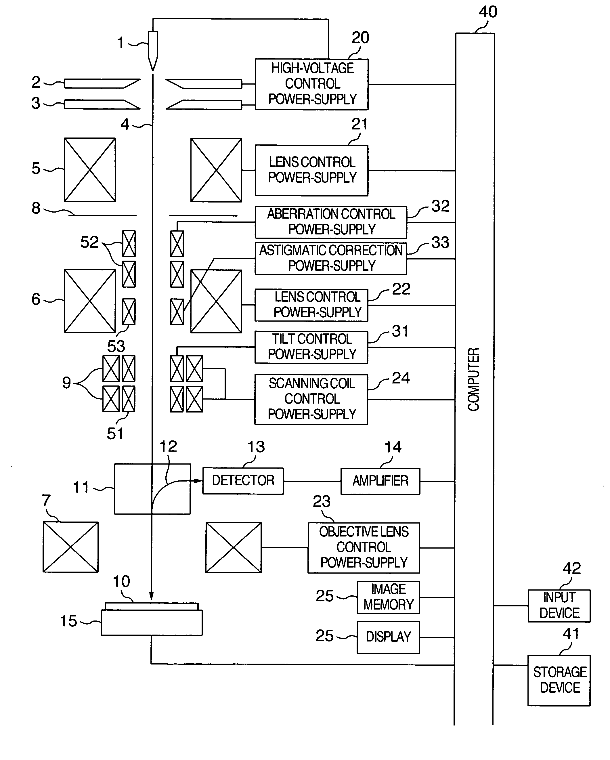
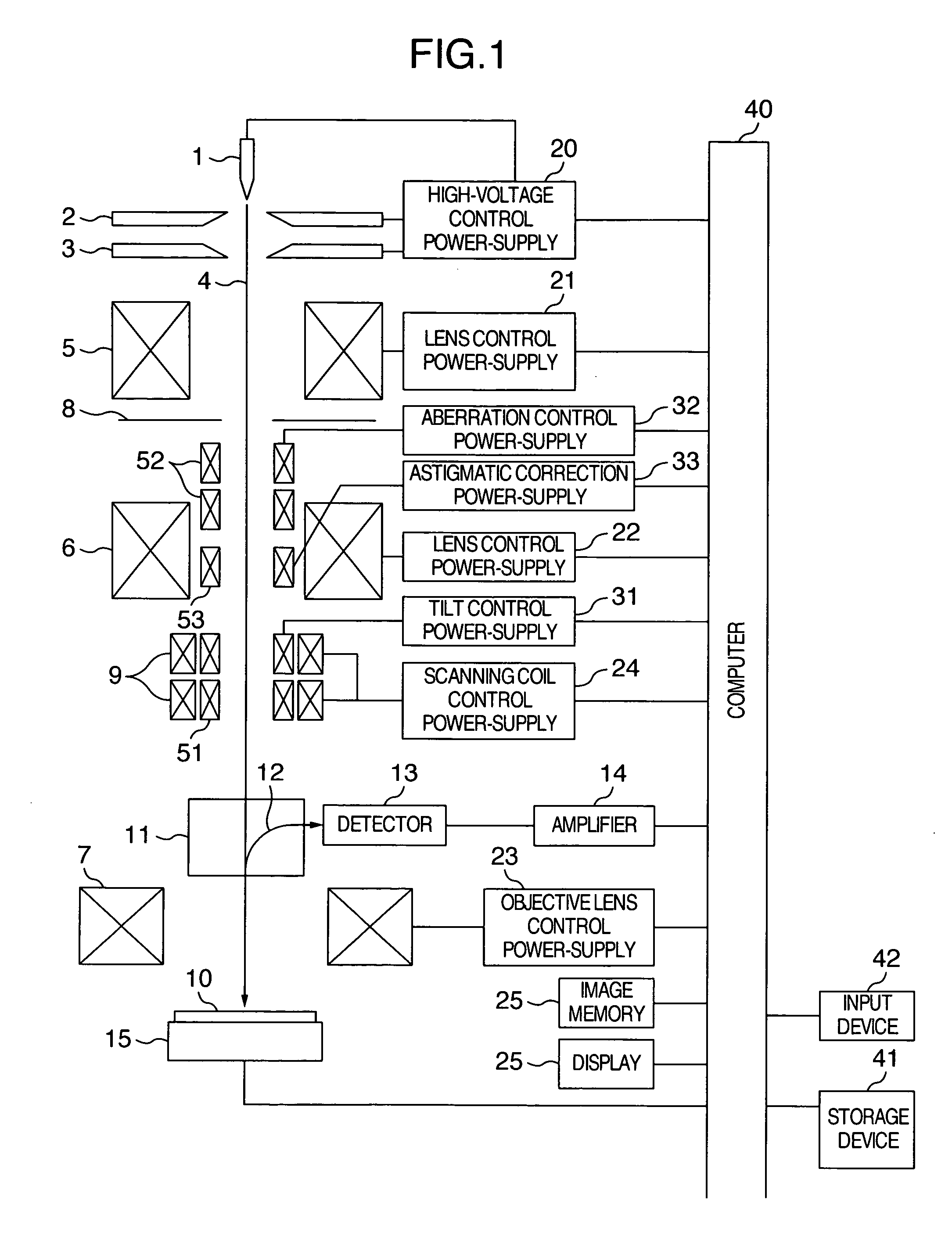
[0033] Concerning an embodiment for correcting the transverse chromatic aberration which occurs at the time of the beam tilt by the scanning electron microscope having the configuration illustrated in FIG. 1, the detailed explanation will be given below, referring to FIG. 4 where its main portion is excerpted.
[0034] In correspondence with the set condition for the beam tilt angle, the deflecting coil 52 deflects the primary beam 4 so that the object point of the converging lens 6 becomes the deflection fulcrum, thereby causing the primary beam 4 to enter the off-axis of the converging lens 6. Next, the primary beam 4, which has entered the off-axis of the converging lens 6, is swung back by the lens effect of the converging lens 6, thereby attaining to a point P1. At the convergence point of the converging lens 6, the deflecting coil 51 is located. The deflecting coil 51 causes the primary beam 4 to enter the off-axis of the objective lens 7. Next, the primary beam 4, which has ent...
embodiment 2
[0037] In the present embodiment, referring to FIG. 4 and FIG. 5, the detailed explanation will be given below concerning an embodiment for automatically adjusting an optical-axis condition for correcting the transverse chromatic aberration which occurs at the time of the beam tilt by the scanning electron microscope having the configuration illustrated in FIG. 1.
[0038] In correspondence with the beam tilt angle relative to the sample, the control conditions for the deflecting coils 52 and 51 illustrated in FIG. 4 are set in accordance with the predetermined relationship therebetween. After that, in order to amend the optical-axis shift thereby to create the optical-axis condition under which the off-axis aberrations of the converging lens 6 and the off-axis aberrations of the objective lens 7 will be cancelled with each other, processing steps S1 to S9 in FIG. 5 are executed.
(i) S1
[0039] In this processing, based on the expression (9), the current change quantities (ΔIc, ΔIobj) ...
embodiment 3
[0048]FIG. 6 illustrates an embodiment of the present invention in an optical-axis adjusting method at the time when the primary beam 4 is tilted on the sample 10 after the transverse chromatic aberration which occurs in the off-axis of the objective lens 7 has been corrected by using a Wien filter 70. In the embodiment in FIG. 6, deflecting coils 61 and 62 are operated so that the object point (beam crossover point) with reference to the objective lens 7 becomes the seeming deflection fulcrum, thereby causing the primary beam 4 to enter the off-axis of the objective lens 7. At this time, the primary beam 4 is swung back in the off-axis of the objective lens 7, thereby attaining to the original point P2 on the sample. The chromatic aberration, however, occurs in the off-axis of the objective lens 7 simultaneously. The Wien filter 70, which is located above the objective lens 7, is operated so that the chromatic aberration which has occurred in the off-axis of the objective lens 7 wi...
PUM
 Abstract
Description
Claims
Application Information