Device for wavelength-selective imaging

a wavelength-selective imaging and device technology, applied in the field of medical imaging techniques, can solve the problems of additional software complexity and processing overhead

Active Publication Date: 2005-12-29
BETH ISRAEL DEACONESS MEDICAL CENT INC
View PDF12 Cites 69 Cited by
  • Summary
  • Abstract
  • Description
  • Claims
  • Application Information

AI Technical Summary

Benefits of technology

[0010] The device that captures photon intensity may be a charge-coupled device. The device may consist of an integrated circuit. The imaging medium may be a fluorescent dye, a phosphorescent substance, a chemoluminscent substance, and / or a scintillant substance. The imaging medium may be a substance introduced into the object. The imaging medium may be a substance inherently present within the object. The object may be an object within a surgical field. The visible light image may be monochromatic. The visible light image may include red, blue and green wavelengths of light. The visible light image may include cyan, magenta, and yellow wavelengths of light. The diagnostic image may include a near-infrared wavelength. The diagnostic image may include an infrared wavelength. The diagnostic image may include a plurality of diagnostic images, each at a different range of wavelengths. The diagnostic image may be formed from one or more diagnostic wavelengths in the visible light range, the object being illuminated with a light source that is depleted in the diagnostic wavelength range.
[0011] The visible light image and diagnostic image may be processed and displayed in a medical imaging system. The medical imaging system may include a display for rendering a composite image including a superposition of the visible light image and the diagnostic image. The medical imaging system may include one or more inputs for controlling at least one of a field of view of the object, a focus of the object, or a zoom of the object. The medical imaging system may include a surgical tool. The visible light image and diagnostic image may be processed and displayed in at least one of a machine vision system, an astronomy system, a military system, a geology system, or an industrial system.

Problems solved by technology

As a significant disadvantage, current CCD systems that combine visible light and emission wavelength imaging typically employ commercially available components, and require at least two separate cameras: a first camera to capture the visible light image and a second camera for capturing the diagnostic emission wavelength which is commonly, though by no means exclusively, in the near-infrared range.
There is also additional software complexity and processing overhead in order to synchronize and superimpose image data streams from the two cameras.

Method used


Image

  • Device for wavelength-selective imaging
  • Device for wavelength-selective imaging
  • Device for wavelength-selective imaging

Examples


Embodiment Construction

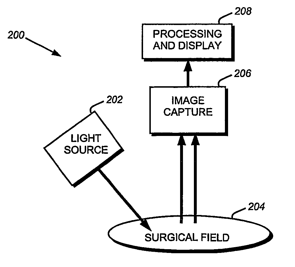
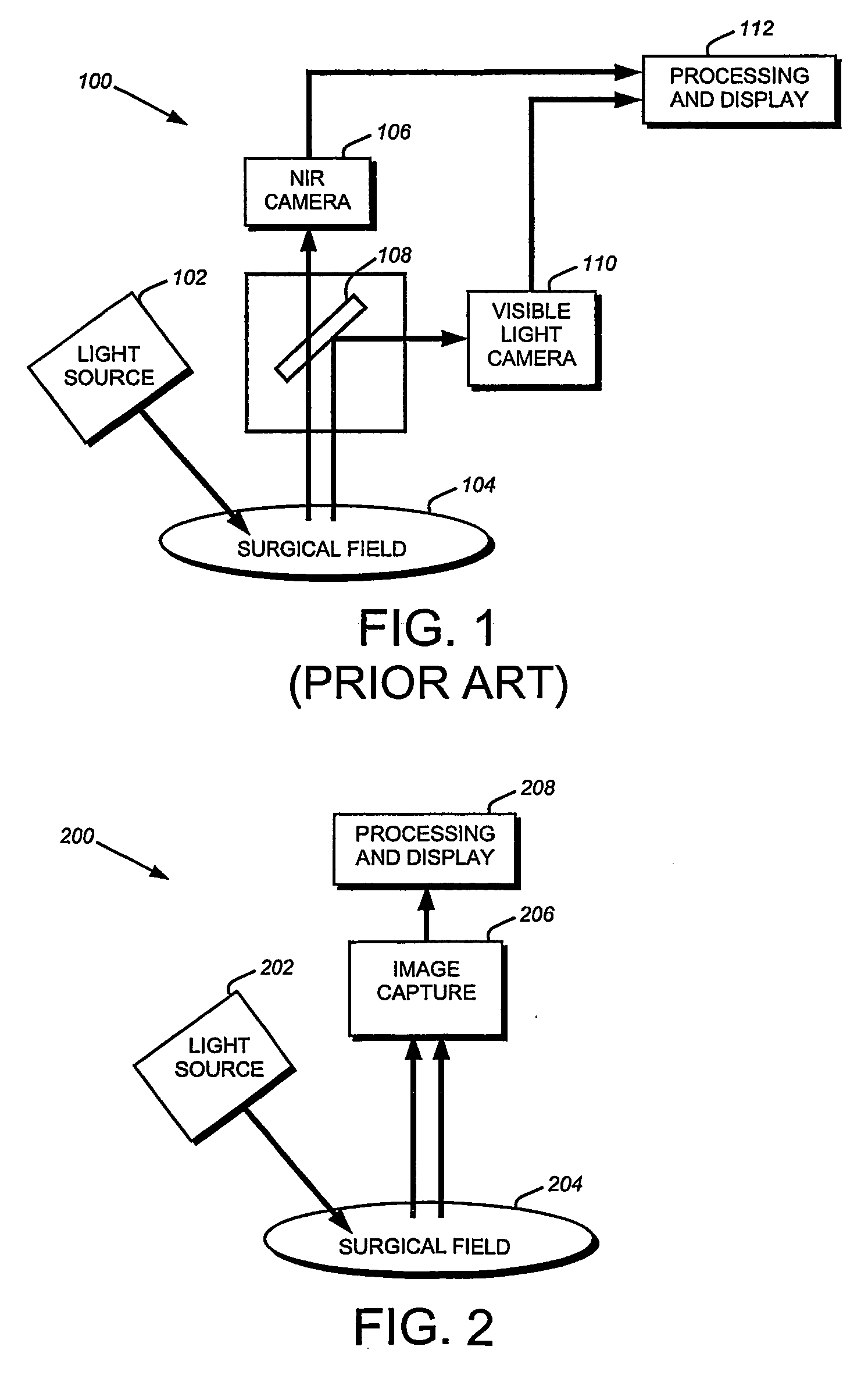
[0026] To provide an overall understanding of the invention, certain illustrative embodiments will now be described, including an image capture device for simultaneously capturing visible-light and near-infrared images. It will be understood that the methods and systems described herein can be suitably adapted to a range of medical imaging applications where visible light tissue images may be usefully combined with diagnostic image information obtained from other specified wavelengths. For example, the systems may be applicable to a wide range of diagnostic or surgical applications where a target pathology, tissue type, or cell may be labeled with a fluorescent dye or other fluorescent substance. More generally, the systems described herein may be adapted to any imaging application where a visible light image may be usefully enhanced with an image of one or more features that are functionally marked to emit photons outside the visible light range by a dye or other material that emit...


PUM

PropertyMeasurementUnit
wavelengthsaaaaaaaaaa

Abstract

An imaging device captures both a visible light image and a diagnostic image, the diagnostic image corresponding to emissions from an imaging medium within the object. The visible light image (which may be color or grayscale) and the diagnostic image may be superimposed to display regions of diagnostic significance within a visible light image. A number of imaging media may be used according to an intended application for the imaging device, and an imaging medium may have wavelengths above, below, or within the visible light spectrum. The devices described herein may be advantageously packaged within a single integrated device or other solid state device, and/or employed in an integrated, single-camera medical imaging system, as well as many non-medical imaging systems that would benefit from simultaneous capture of visible-light wavelength images along with images at other wavelengths.

Description

GOVERNMENT INTERESTS [0001] The United States Government has certain rights in this invention pursuant to Department of Energy Grant # DE-FG02-01ER63188.BACKGROUND OF THE INVENTION [0002] A number of medical imaging techniques have emerged for capturing still or moving pictures using dyes that can be safely introduced into living tissue. For example, fluorescent dyes may be adapted for sequestration or preferential uptake at a location of medical interest, such as a lesion. The location may then be exposed to a light source that stimulates fluorescence of the dye to permit visualization that enhances a feature of the location. Other emerging techniques employ phosphorescent, chemoluminescent, or scintillant substances to generate photons at one or more wavelengths suitable for imaging. These techniques have proven useful for medical imaging and surveillance, with applications including lesion imaging, calcium deposit imaging, and blood flow imaging. [0003] Such imaging techniques ha...

Claims


Application Information

Patent Timeline
Patent Type & Authority Applications(United States)
IPC IPC(8): A61B5/00G01J3/36G01N21/64G02B5/20G02B23/12G02F1/01H01L27/146H01L27/148H01L31/00H01L31/101H01L31/111
CPCA61B5/0059H01L31/111G01N21/6428G01N21/6456G02B5/201G02B23/12H01L27/14621H01L27/14625H01L27/14647H01L27/14806H01L27/14837H01L27/14843H01L27/14868H01L31/101G01J3/36A61B5/7425
Inventor FRANGIONI, JOHN V.
Owner BETH ISRAEL DEACONESS MEDICAL CENT INC
Why Eureka
Try Eureka