Quick removable chuck assembly and its cutting tool

a chuck and assembly technology, applied in the field of chucks, can solve the problems of high manufacturing cost, insufficient clamping force provided by the chuck, complicated structure, etc., and achieve the effect of simplifying the structure of the chuck, facilitating and quick assembly of the cutting tool, and high manufacturing cos

Inactive Publication Date: 2005-12-29
CHUM POWER MASCH CORP
View PDF15 Cites 28 Cited by
  • Summary
  • Abstract
  • Description
  • Claims
  • Application Information

AI Technical Summary

Benefits of technology

[0006] The primary objective of the present invention is to overcome the shortcomings of the prior-art clamper chuck structure carrying a high manufacturing cost and having insufficient clamping force. The present invention intends to use a solution totally different from the prior art to overcome the foregoing shortcomings and achieve the objectives of simplifying the structure of the chuck, making the assembling and positioning of the cutting tool convenient and quick, providing a precise positioning in the axial direction and the direction of the rotation of the cutting tool, and improving the stability of installing the chuck onto the cutting tool. More particularly, the positioning along the direction of the rotation can effectively prevent the stripping and idle operation of the cutting tool, and thus improving the torque of the cutting tool. In addition, the present invention controls the installation and removal of the cutting tool by rotating a positioning sleeve; after the positioning sleeve is rotated to an appropriate angle, the present invention also provides a solution for limiting the angle of rotation appropriately instead of freely rotating in 360 degrees. Such arrangement assures the positioning of the related objects and prevent any damage caused by an over rotation.

Problems solved by technology

Therefore, the structure of the aslant guided hole and the clamper requires a high precision which will relatively increase the manufacturing cost.
If the cutting tool encounters a larger resistance in its operation, the clamper and the cutting tool probably will be stripped, which indicates an insufficient clamping force provided by the clamper.
Therefore, many designs for improving the torque of the clamper chuck are introduced, but most of these designs come with a very complicated structure and have a very high manufacturing cost.

Method used


Image

  • Quick removable chuck assembly and its cutting tool
  • Quick removable chuck assembly and its cutting tool
  • Quick removable chuck assembly and its cutting tool

Examples


Embodiment Construction

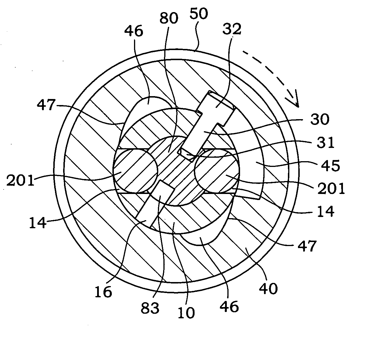
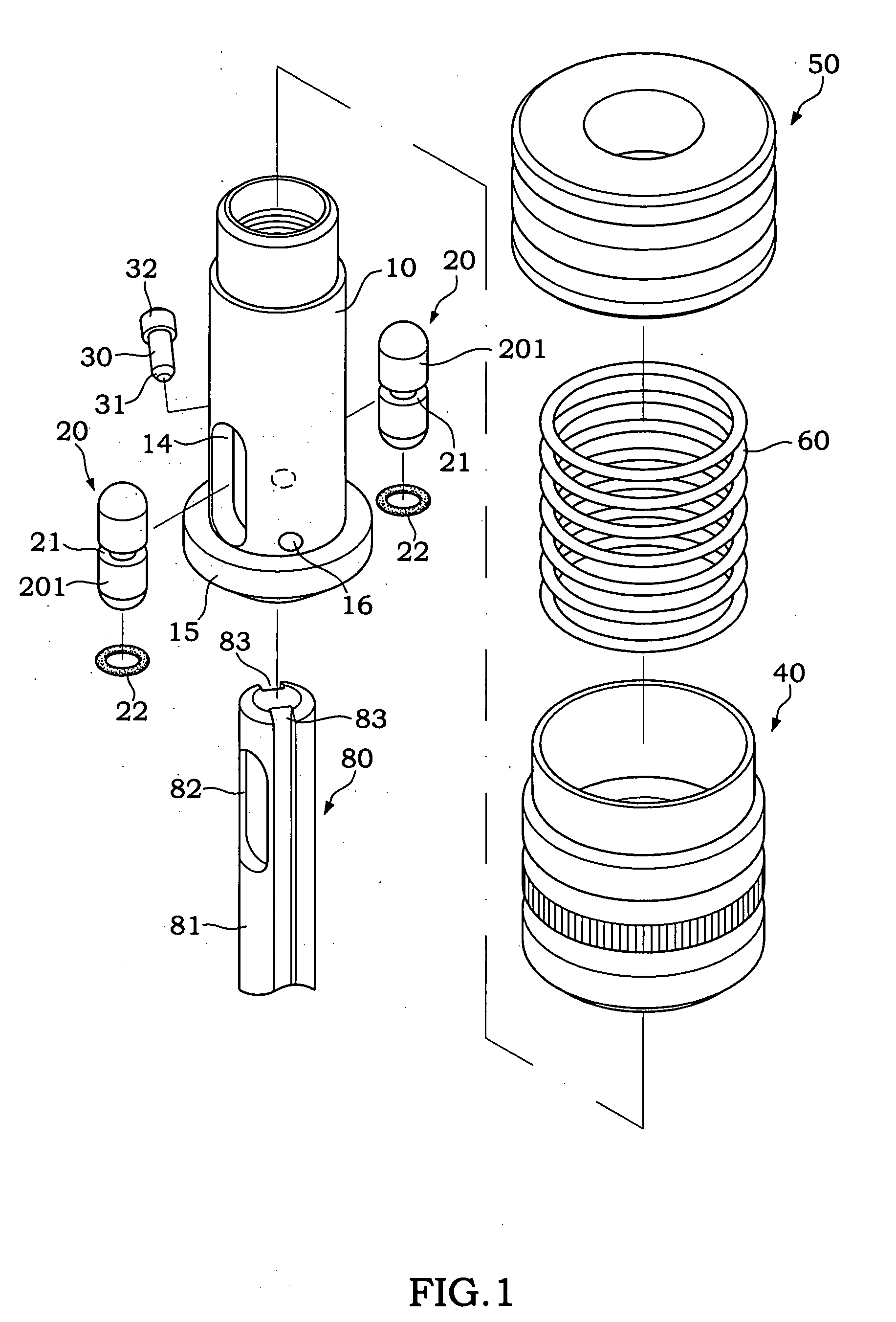
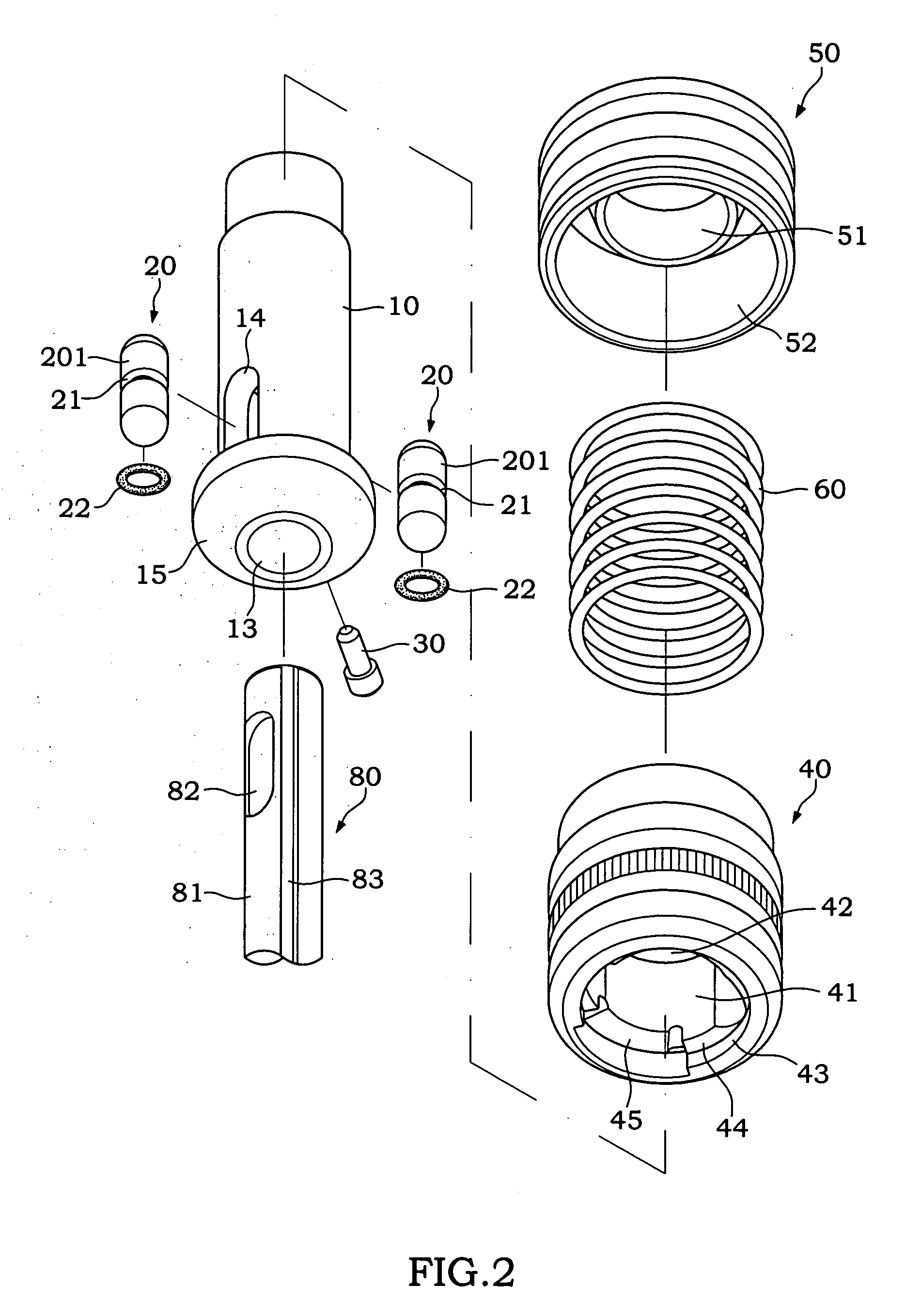
[0027] The present invention relates to a quick removable chuck assembly, comprising: [0028] a main body 10 as shown in FIGS. 1, 2, 5 and 6, with an axial hole passing through its center, and the axle hole can be divided into an upper section and a lower section, wherein the upper section is a power axle hole 12 for connecting a power axle of a transmission device (not shown in the figures) and the lower section is cutting tool receiving hole 13 for passing a cutting tool 80 (such as a drill head) through a positioning section 81 disposed at an end other than the operating end, and the main body 10 has a stop member 15 with an expanded diameter; [0029] a positioning assembly as shown in FIGS. 1, 2 and 6A, having a device hole disposed at a corresponding position on the wall of the cutting tool receiving hole 13, and a sliding device 20 disposed in each device hole, and the sliding device 20 could be a rolling needle 201 as shown in FIG. 1 or a rolling ball 202 as shown in FIG. 10 or...


PUM


Abstract

The present invention discloses a quick removable chuck assembly and its cutting tool comprises a cutting tool with its positioning section passing through an axial hole of a main body; a sliding device being disposed on a wall of the main body and capable of moving back and forth horizontally along the axis of the main body; a device embedding groove being disposed at a positioning section of the cutting tool for embedding the sliding device; and a positioning sleeve being axially disposed outside the main body for controlling the sliding device to move back and forth by a rotary action; thereby the present invention can achieve the objectives of installing and removing the cutting tool in a quick and convenient manner.

Description

BACKGROUND OF THE INVENTION [0001] 1. Field of the Invention [0002] The present invention relates to a chuck, more particularly to a chuck that allows users to rotate and control a lower positioning sleeve of the chuck, so that the chuck can install or remove a drilling tool (such as a drill head). [0003] 2. Description of the Related Art [0004] In general, a chuck assembly of a traditional drilling tool (such as a drill head) usually connects a main body with a power axle of a transmission device, and the main body comprises a plurality of aslant guided holes on the walls of the main body, a clamper disposed in each aslant guided hole, and the clamper is controlled by a driving ring coaxially disposed outside the main body. In other words, a synchronous aslant movement can be produced along an axis not parallel to the main body by rotating the driving ring, so that when a plurality of clampers move slantwise towards the axial direction of the main body, a cutting tool is clamped. C...

Claims


Application Information

Patent Timeline
Patent Type & Authority Applications(United States)
IPC IPC(8): B23B31/107B23B31/171B25D17/08
CPCB23B31/1071B23B31/1072Y10T279/17803B25D2217/0042B25D2217/0049B25D17/088B23B31/10741
Inventor LIN, YUAN-HO
Owner CHUM POWER MASCH CORP
Why Eureka
Try Eureka