Bicycle electrical generator hub

a generator hub and bicycle technology, applied in the direction of cycle equipment, optical signal, magnetic circuit shape/form/construction, etc., can solve the problems of large increase in manufacturing costs, changes in the visual appearance of bicycles, and increase the number of bicycle manufacturing operations, so as to reduce the manufacturing costs of bicycles and not damage the visual appeal of bicycles.

Active Publication Date: 2005-12-29
SHIMANO INC
View PDF15 Cites 59 Cited by
  • Summary
  • Abstract
  • Description
  • Claims
  • Application Information

AI Technical Summary

Benefits of technology

[0009] One object of the present invention is to provide a bicycle, a bicycle gearshift system, and a bicycle derailleur that are able to reduce the manufacturing costs of bicycles while not damaging the visual appeal of the bicycles.

Problems solved by technology

Because of this, in addition to the normal bicycle assembly operations, it is necessary to perform installations operation for the gearshift system devices, and perform wiring operations, greatly increasing the number of manufacturing operations for the bicycle, leading to large increases in manufacturing costs.
Moreover, the installation of the gearshift systems greatly changes the visual appearance of the bicycles, reducing their visual appeal.

Method used


Image

  • Bicycle electrical generator hub
  • Bicycle electrical generator hub
  • Bicycle electrical generator hub

Examples


Embodiment Construction

[0062] Selected embodiments of the present invention will now be explained with reference to the drawings. It will be apparent to those skilled in the art from this disclosure that the following descriptions of the embodiments of the present invention are provided for illustration only and not for the purpose of limiting the invention as defined by the appended claims and their equivalents.

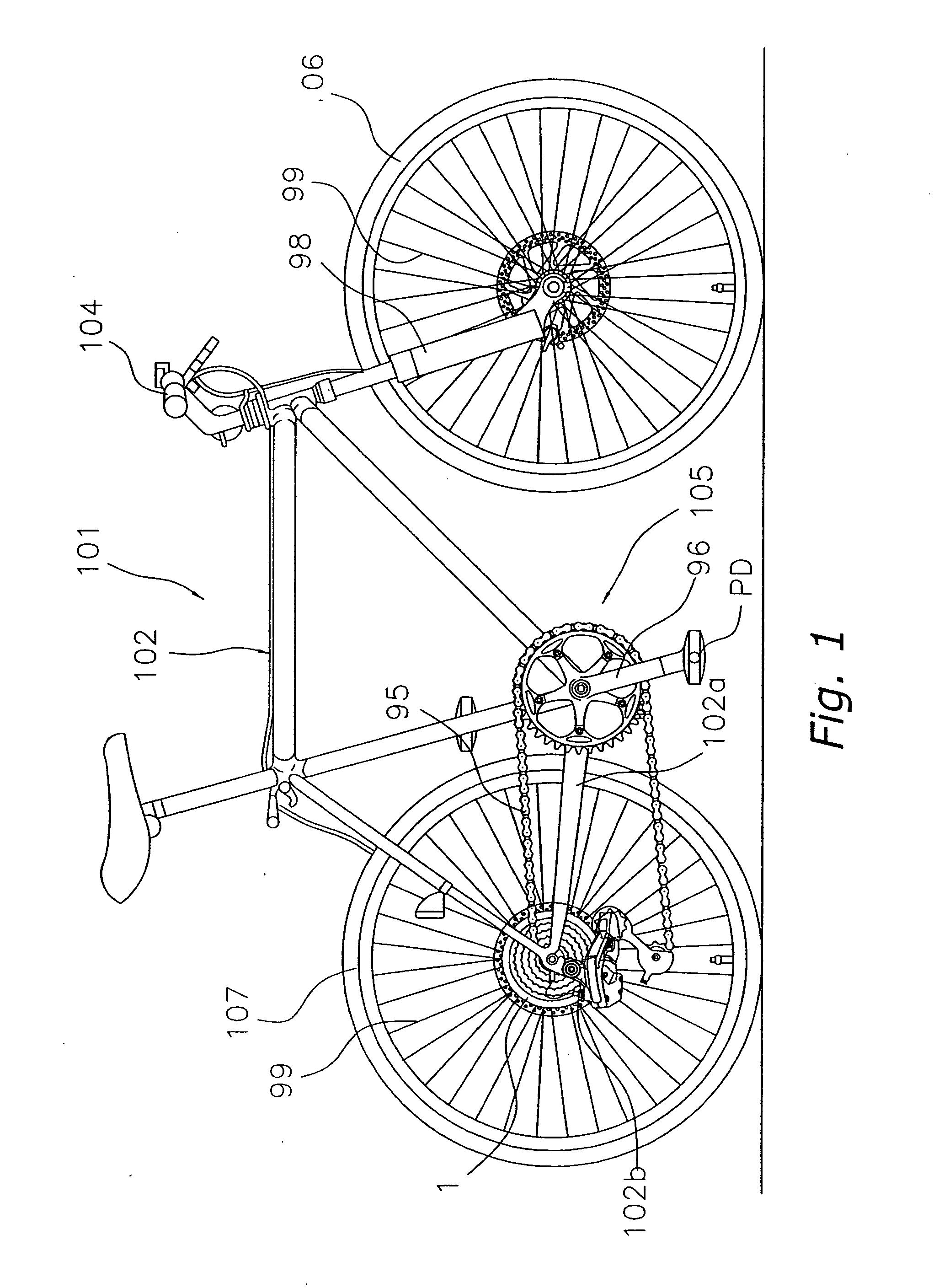
[0063] Referring initially to FIG. 1, a bicycle 101 is illustrated in accordance with a first embodiment of the present invention. The bicycle 101 is equipped with a diamond-shaped frame 102 with a suspension fork 98 pivotally coupled thereto. A handlebar 104 is rigidly attached to the suspension fork 98 to steer the bicycle 101. A drive train (part) 105 is attached to the frame. The drive train 105 includes a chain 95, a gear crank or crank set 96 onto which a pedal PD is mounted, a electrically powered rear derailleur (an example of the electrically powered gearshift mechanism) 97, as well as o...


PUM


Abstract

A bicycle gearshift system is mounted on the rear part of the frame of the bicycle. The bicycle gearshift system includes an electrically powered rear derailleur, a rear hub, a charger part, and a gearshift control part. The electrically powered rear derailleur is mounted on the rear part of the frame. The rear hub is also mounted to the rear part of the frame. The rear hub has an electrical generator mechanism that generates electricity through the rotation of the wheel. The charger part is mounted on the rear hub and stores the electrical energy that was generated by the generator part. The gearshift control part is equipped on the electrically powered rear derailleur, where gearshift control of the electrically powered rear derailleur is performed through the energy that is stored in the charger part.

Description

CROSS-REFERENCE TO RELATED APPLICATIONS [0001] This application claims priority to Japanese Patent Application No. 2004-191685. The entire disclosure of Japanese Patent Application No. 2004-191685 is hereby incorporated herein by reference. BACKGROUND OF THE INVENTION [0002] 1. Field of the Invention [0003] The present invention generally relates to a bicycle electrical generator hub mounted in the center part of a wheel of a bicycle. More specifically, the present invention relates to a bicycle gearshift system that is driven electrically and equipped on the rear hub part of a bicycle frame. [0004] 2. Background Information [0005] Some bicycles are equipped with gearshift mechanisms such as derailleurs or hubs with internal gearshifters. Electrically powered gearshift devices are already known. In conventional gearshift systems that include electrically powered gearshift mechanisms, automatic gearshift control, for example, is performed by the electrically driven gearshift mechanis...

Claims


Application Information

Patent Timeline
Patent Type & Authority Applications(United States)
IPC IPC(8): B62J6/12B62J99/00B62M1/36B62M9/122B62M9/123B62M9/1242B62M9/126B62M25/08H02K1/14H02K7/18H02K21/22
CPCB62M25/08H02K7/1846H02K1/145
Inventor KITAMURA, SATOSHIUENO, KOKENTAKEDA, KAZUHIROFUKUDA, MASAHIKO
Owner SHIMANO INC
Why Eureka
Try Eureka