
Image correction method for compensating for misalignment of pixels in holographic digital data storage system

a technology of holographic digital data and image correction, applied in the field of image correction, can solve problems such as increasing the size of the ccd array, reducing the processing speed of image data, and serious degradation of data detected in the ccd array

Active Publication Date: 2005-12-29
TAIWAN SEMICON MFG CO LTD
View PDF7 Cites 6 Cited by
  • Summary
  • Abstract
  • Description
  • Claims
  • Application Information

AI Technical Summary

Benefits of technology

[0011] It is, therefore, an object of the present invention to provide an image correction method, which compensates for a misalignment of charge coupled device pixels when detecting a page-based information image, recorded on a holographic storage medium, by using a charge coupled device through one-to-one pixel matching signal processing in a holographic digital data storage system.

Problems solved by technology

However, a shift multiplexing system using the above-described 1:1 pixel matching is problematic in that there occurs serious degradation of data detected in a CCD array in case a misalignment between a data pixel and a CCD pixel reaches approximately ½ of the size of the CCD pixel.
However, the above-described image correction method for the misalignment of pixels using the optical model of Burr is problematic in that it takes lots of time to calculate original signal intensities passing through the SLM with the values of the optical fields detected at the detector pixels, thus decreasing an image data processing speed.
This method is advantageous in that it has a small amount of calculation compared to the optical modeling method of Burr and can restore data relatively precisely, but is problematic in that it must oversample original image data at the time of reproduction, thus increasing the size of a CCD array.

Method used


Image

  • Image correction method for compensating for misalignment of pixels in holographic digital data storage system
  • Image correction method for compensating for misalignment of pixels in holographic digital data storage system
  • Image correction method for compensating for misalignment of pixels in holographic digital data storage system

Examples


Embodiment Construction

[0020] A preferred embodiment of the present invention will now be described in detail with reference to the accompanying drawings.

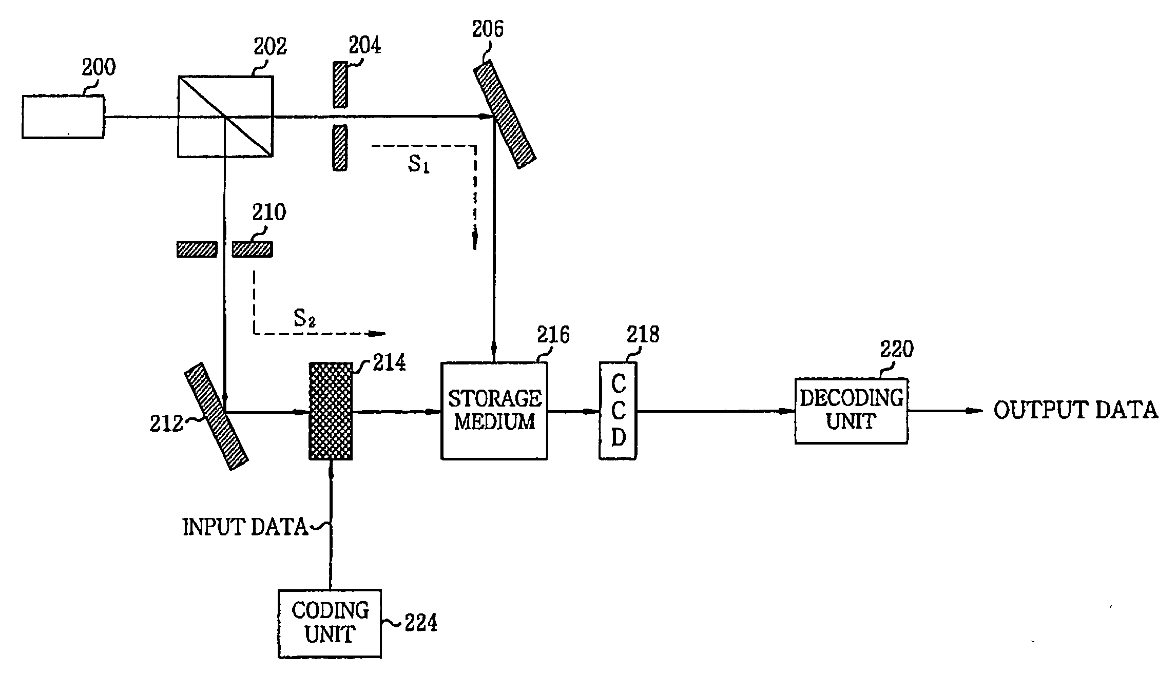
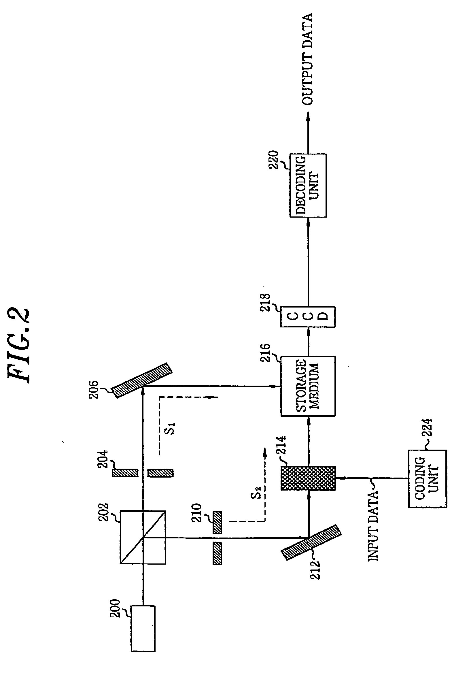
[0021]FIG. 2 illustrates a block diagram of an HDDS system to which the preferred embodiment of the present invention is applied. Hereinafter, with reference to FIG. 2, operations of recording / reproducing holographic data in the HDDS system are described.

[0022] First, a beam splitter 202 splits laser light incident from a light source 200 into a reference beam and an object beam. The reference beam, which is a vertically polarized beam, is provided along a reference beam processing path S1, and the object beam is provided along an object beam processing path S2. Further, in the reference beam processing path S1, a shutter 204 and a reflective mirror 206 are provided in a direction in which the reference beam proceeds. Through this optical transmission path, the reference beam processing path S1 reflects the reference beam required for the recording or ...


PUM

PropertyMeasurementUnit
speedaaaaaaaaaa
sizeaaaaaaaaaa
optical modelaaaaaaaaaa

Abstract

For compensating for misalignment of pixels at the time of reproduction in a Holographic Digital Data Storage (HDDS) system, and thereby correcting an image, a stored page-based image is detected using a Charge Coupled Device (CCD) through a one-to-one (1:1) pixel matching between data pixels and CCD detector pixels at the time of reproduction. And then, in case the misalignment of pixels occurs during the 1:1 pixel matching, an amount of the misalignment d (0≦d<1) between a corresponding data pixel and a corresponding CCD detector pixel is calculated. Further, an interference influence of a neighboring pixel on the corresponding CCD detector pixel is calculated based on the calculated amount of the misalignment, to thereby correct image data of the CCD detector pixel. And last, a misalignment influence in accordance with the amount of the misalignment is compensated for, to thereby correct the image data of the CCD detector pixel.

Description

FIELD OF THE INVENTION [0001] The present invention relates to a holographic digital data storage system; and, more particularly, to an image correction method, which compensates for a misalignment of charge coupled device pixels when detecting a page-based information image, recorded on a holographic storage medium, using a charge coupled device through one-to-one pixel matching signal processing in a holographic digital data storage system. BACKGROUND OF THE INVENTION [0002] From the viewpoint of the data recording / reproduction principle, a Holographic Digital Data Storage (HDDS) system is typically a page-oriented memory using a volumetric hologram principle. An HDDS system can implement a super high input / output speed of 1 Gbps or above by using a parallel data processing scheme as an input / output scheme, and can be constructed without a mechanical driving unit to thereby implement a very fast data access time of 100 μs or less. And accordingly, the HDDS system has attracted att...

Claims


Application Information

Patent Timeline
Patent Type & Authority Applications(United States)
IPC IPC(8): G03H1/22G03H1/26G11B7/005G11B7/0065H04N1/04H04N5/89
CPCG11B7/0065G11B7/005G03H1/26
Inventor YOON, PIL-SANG
Owner TAIWAN SEMICON MFG CO LTD
Learn More