Lens barrel and photographing apparatus incorporating the same

a technology of lens barrel and photographing apparatus, which is applied in the direction of mountings, optics, instruments, etc., can solve the problems of driving device cannot provide satisfactory operation characteristics, rearmost focusing lens unit size and weight increase, etc., to achieve good driving characteristics, reduce thrust, and increase leakage flux

Inactive Publication Date: 2005-12-29
CANON KK
View PDF3 Cites 11 Cited by
  • Summary
  • Abstract
  • Description
  • Claims
  • Application Information

AI Technical Summary

Benefits of technology

[0024] The present invention is directed to a lens barrel and a photographing apparatus in which the balance of the center of gravity of a focusing lens unit is improved to obtain good driving characteristics. The present invention is also directed to a lens barrel and a photographing apparatus including a small actuator that does not cause an increase in leakage flux or a decrease in thrust.

Problems solved by technology

Meanwhile, in the case of an interchangeable lens barrel, a rearmost focusing lens unit tends to have an increased size and an increased weight.
Accordingly, in some cases, due to the unbalance of the focusing lens unit with respect to the center of gravity, the driving device cannot provide satisfactory operation characteristics.
Furthermore, in the case of an interchangeable lens barrel, the rearmost focusing lens unit tends to have an increased size and an increased weight as described above.
Accordingly, an actuator for driving the focusing lens unit is required to have a large output, thus resulting in an increase in size.
In this instance, if the plate thickness of the yoke exceeds a given value, it becomes difficult to mass-produce U-shaped yokes.

Method used


Image

  • Lens barrel and photographing apparatus incorporating the same
  • Lens barrel and photographing apparatus incorporating the same
  • Lens barrel and photographing apparatus incorporating the same

Examples


first embodiment

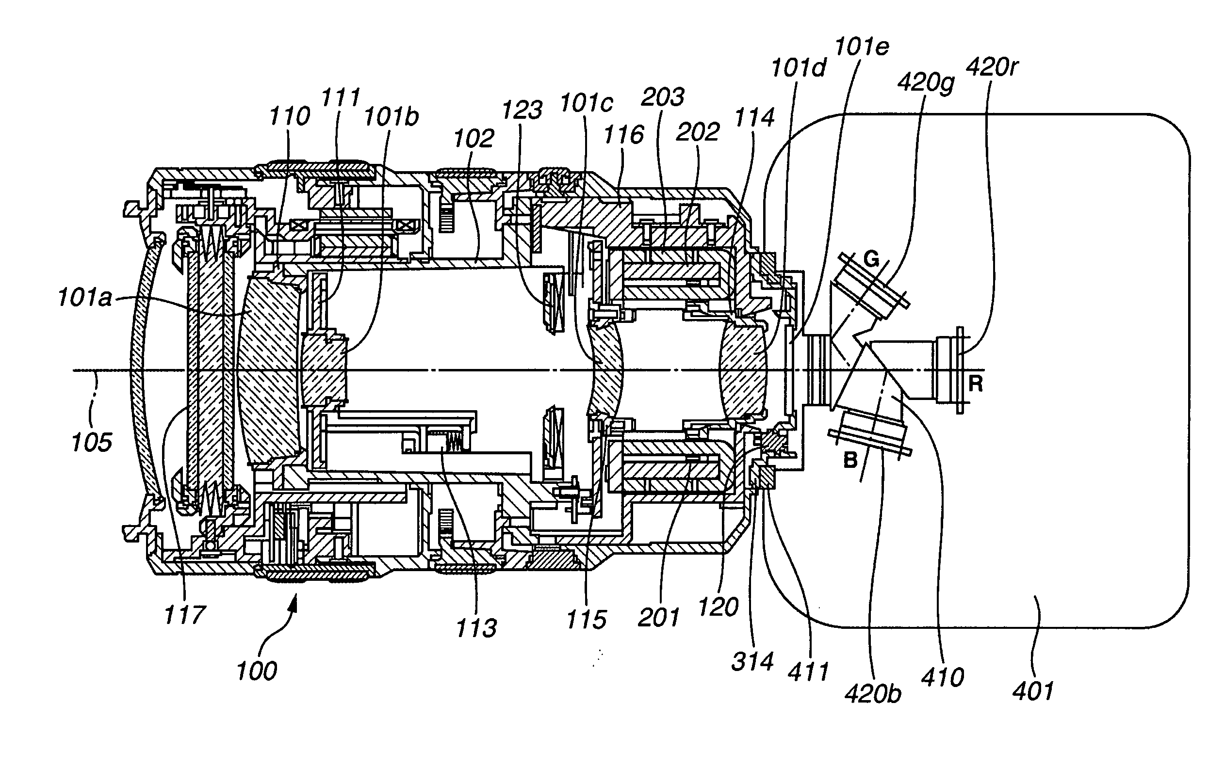
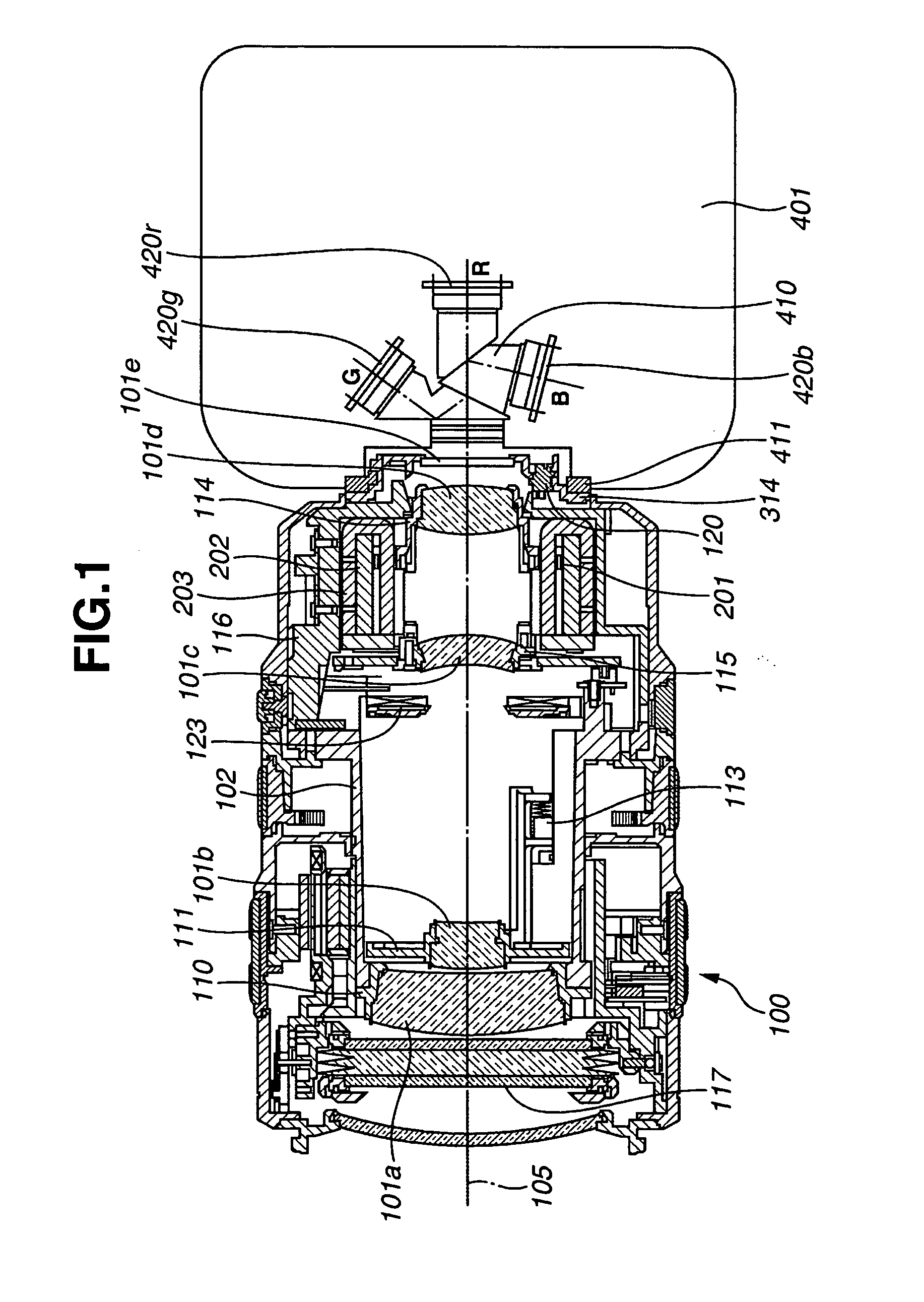
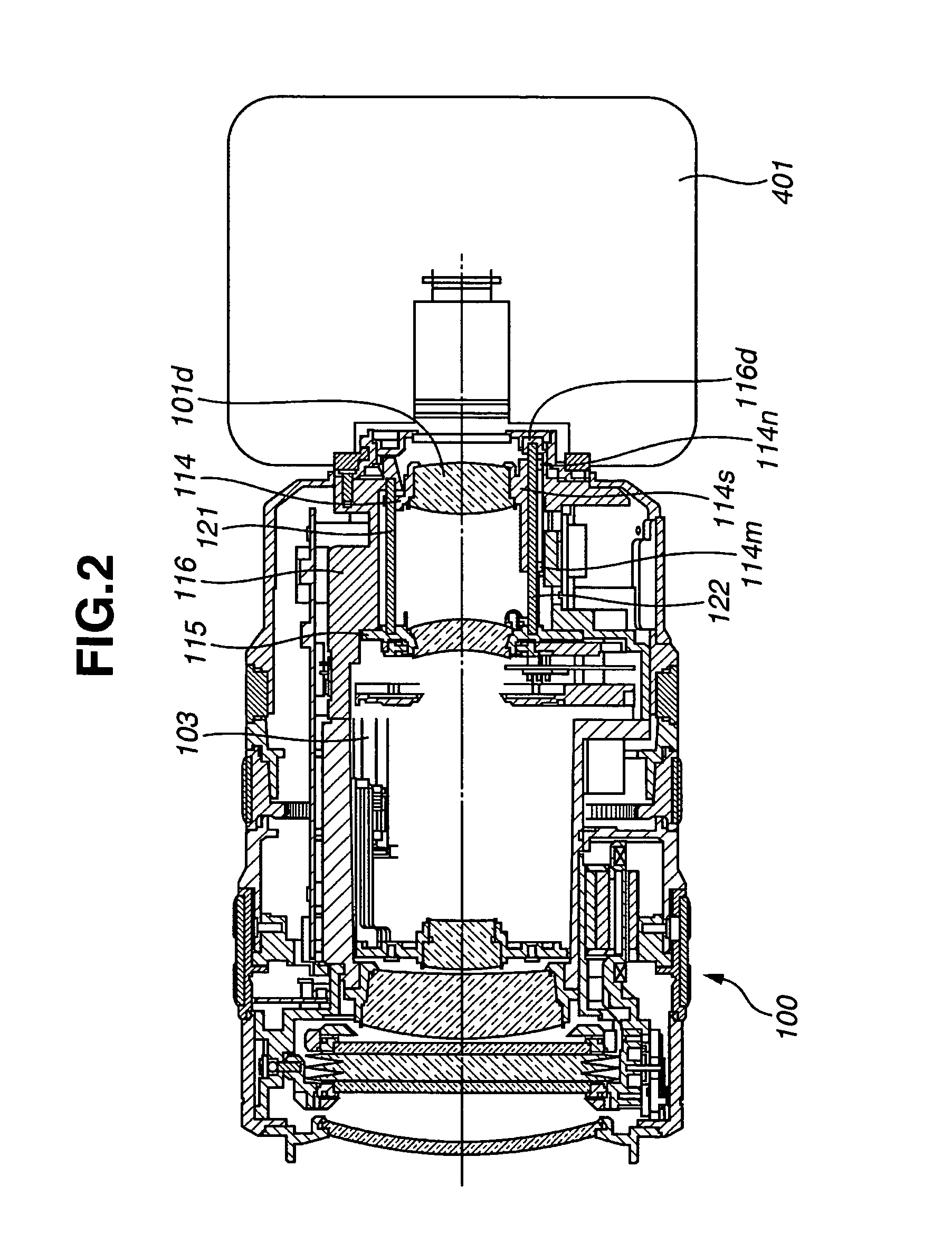
[0035]FIG. 1 is a longitudinal sectional view of an interchangeable lens barrel 100 according to a first embodiment of the invention. In FIG. 1, the lens barrel 100 is coupled to a camera body 401 via a coupling mount. The lens barrel 100 includes a zoom lens as an imaging optical system, and the camera body 400 includes an image capture unit. FIG. 2 is a transverse sectional view of the lens barrel 100.

[0036] Referring to FIGS. 1 and 2, the zoom lens includes four lens units, i.e., a fixed positive lens unit 101a, a movable negative lens unit 101b, a fixed positive lens unit 101c, and a movable positive lens unit 101d. More specifically, the fixed positive lens 101a is a fixed front lens unit. The movable negative lens unit 101b is a variator lens unit movable along an optical axis 105 for zooming. The fixed positive lens unit 101c is a fixed afocal lens unit. The movable positive lens 101d is a focusing lens unit movable along the optical axis 105 for adjusting focus and keeping ...

second embodiment

[0052] A second embodiment of the present invention relates to an example of the structure of a linear actuator that is applicable to the lens barrel of the first embodiment. FIG. 5 is a perspective view of the linear actuator according to the second embodiment.

[0053] With regard to a U-shaped yoke, for example, if the RR moving ring 114 is about 15 g in weight and two linear actuators require generating a force of about 80 gf (gram-force), the plate thickness of a neodymium magnet becomes about 3 mm and the plate thickness of the U-shaped yoke also becomes about 3 mm. In this instance, two legs of the U-shaped yoke are required to have an interval of about 5 mm so as to secure a space for the magnet and an actuation portion of the coil. It is difficult in terms of shape to produce such a U-shaped yoke from one sheet metal.

[0054] The second embodiment is directed to solving this difficulty in the plate thickness by using an auxiliary yoke.

[0055] Referring to FIG. 5, a first U-sha...


PUM


Abstract

A lens barrel includes a mount member configured to couple the lens barrel to a camera body, the mount member having a coupling surface for coupling with the camera body, a lens holding frame holding a lens and movable along an optical axis, the lens holding frame having a sleeve portion, the sleeve portion having a front end and a rear end, and a guide bar configured to guide the sleeve portion of the lens holding frame along the optical axis. The guide bar extends to a location nearer to an image plane than the coupling surface of the mount member. The rear end of the sleeve portion is disposed nearer to the image plane than the lens.

Description

BACKGROUND OF THE INVENTION [0001] 1. Field of the Invention [0002] The present invention relates to a lens barrel and a photographing apparatus incorporating the lens barrel. For example, the present invention relates to a lens barrel configured to drive an optical element, such as a focusing lens or a zoom lens, with a linear actuator along an optical axis, and to a photographing apparatus incorporating such a lens barrel. In particular, the present invention relates to an interchangeable lens barrel having an imaging optical system configured to bayonet-couple to a camera body having an image capture unit via a coupling mount, and to a photographing apparatus incorporating the interchangeable lens barrel. [0003] 2. Description of the Related Art [0004] Heretofore, a variety of zoom lenses for video cameras or lenses for digital still cameras have been developed. Among them, a typical zoom lens for video cameras includes four lens units, i.e., in order from the object side, a fixe...

Claims


Application Information

Patent Timeline
Patent Type & Authority Applications(United States)
IPC IPC(8): G02B7/10G02B15/14
CPCG02B7/102
Inventor ICHINOSE, HARUNOBUFUJIWARA, DAISUKE
Owner CANON KK
Why Eureka
Try Eureka