Wireless local area network repeater

a repeater and local area network technology, applied in the field of repeaters, can solve the problems of lack of performance, spontaneous generation and transmission of wireless network nodes, and rarely realized performance levels, and achieve the effects of high-speed communication, small repeater and relatively inexpensive cos

Inactive Publication Date: 2005-12-29
THE TRUSTEES OF THE UNIV OF PENNSYLVANIA +1
View PDF99 Cites 101 Cited by
  • Summary
  • Abstract
  • Description
  • Claims
  • Application Information

AI Technical Summary

Benefits of technology

[0010] The wireless repeater of the present invention therefore enables high-speed communication among transmitters and receivers that might otherwise be isolated from one another in a conventional WLAN environment. Further, the repeater is small and relatively inexpensive, and avoids spontaneous transmission by monitoring and responding in reaction to the transmissions.

Problems solved by technology

While the specifications of products utilizing the above standard wireless protocols commonly indicate data rates on the order of, for example, 11 MBPS and ranges on the order of, for example, 100 meters, these performance levels are rarely, if ever, realized.
This lack of performance is due to attenuation of the radiation paths of RF signals, which are typically in the range of 2.4 GHz, in an indoor environment Base to receiver ranges are generally less than the coverage range required in a typical home, and may be as little as 10 to 15 meters.
One significant complication is that the system receivers and transmitters operate at the same frequency for a WLAN utilizing 802.11 or 802.16 WMAN wireless protocol.
The packets from each wireless network node are spontaneously generated and transmitted and are not temporally predictable.
While existing CDMA systems employ directional antennas and physical separation of the receive and transmit antennas to achieve this isolation, such techniques are not practical for WLAN repeaters in many operating environments such as in the home where lengthy cabling is not desirable or may be too costly.

Method used


Image

  • Wireless local area network repeater
  • Wireless local area network repeater
  • Wireless local area network repeater

Examples


Embodiment Construction

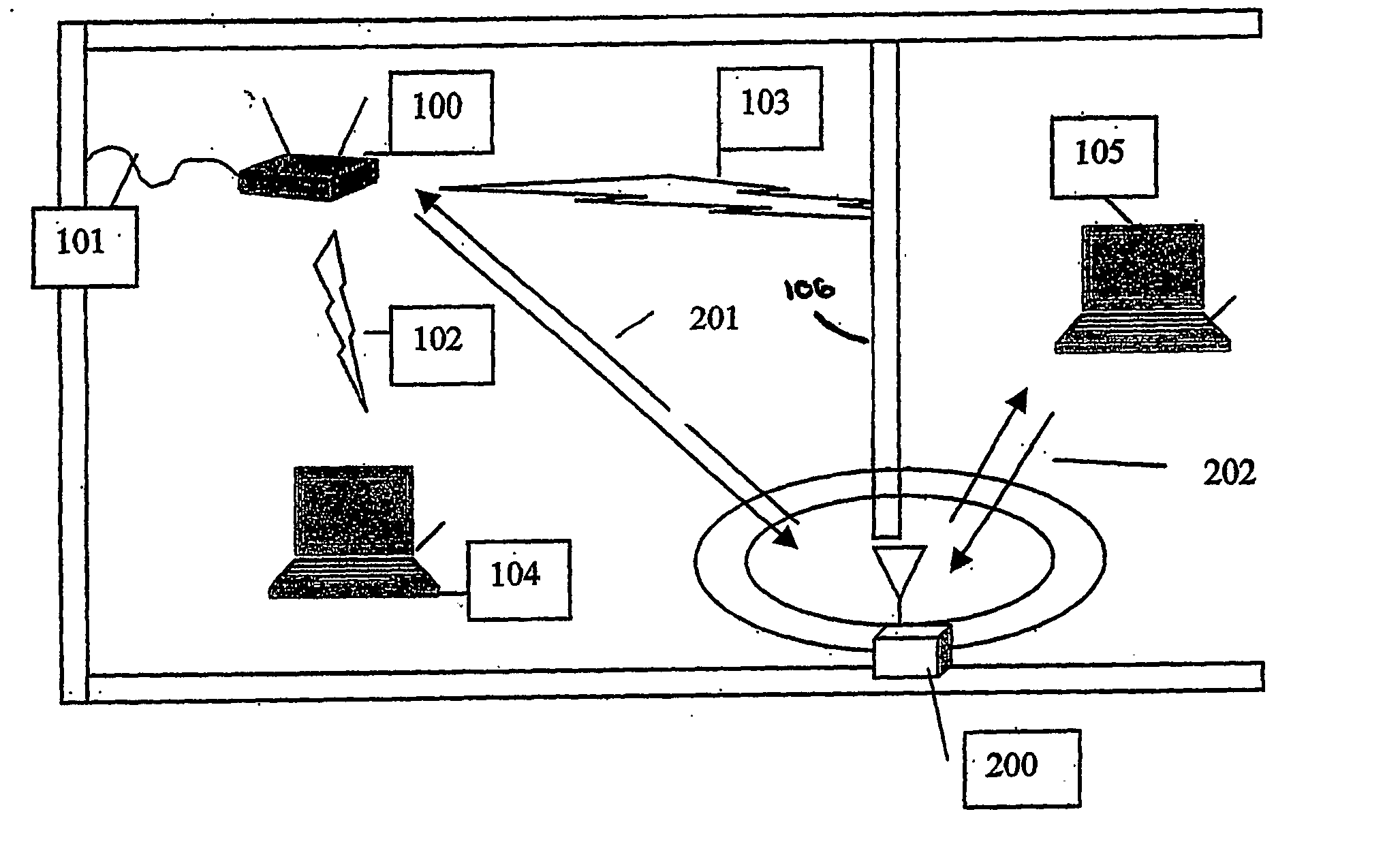
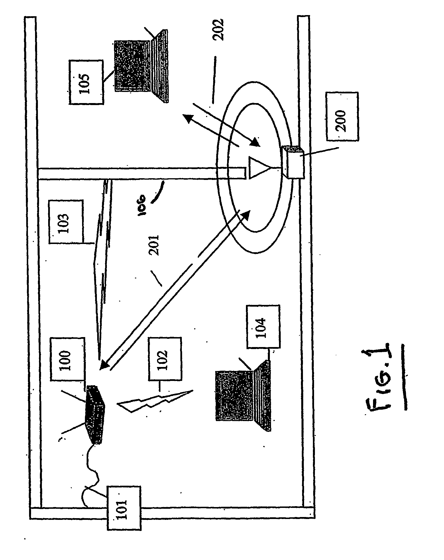
[0015] Referring now to FIG. 1, a wide area connection 101, which could be an Ethernet connection, a T1 line, a wideband wireless connection or any other electrical connection providing data communication, is connected to a wireless gateway, or access point, 100. The wireless gateway 100 sends RF signals, such as IEEE 802.11 packets or signals based upon Bluetooth, Hyperlan, or other wireless communication protocols, to client devices 104, 105, which may be personal computers, personal digital assistants, or any other device capable of communicating with other like devices through one of the above mentioned wireless protocols. Respective propagation, or RP, paths to each of the client devices are shown as 102, 103.

[0016] While the signal carried over RF path 102 is of sufficient strength to maintain high-speed data packet communications between the client device 104 and the wireless gateway 100, the signals carried over the RF path 103 and intended for the client device 105 would b...


PUM


Abstract

A repeater (200) facilitates wireless communication between a first communication device (100) and a second communication device (105) in a wireless network using a time division duplex protocol for data transmission. The repeater (200) includes a receiver (310, 315) for receiving a signal on either of at least two bi-directional communication frequencies simultaneously. A signal detector (362) is operatively coupled to the receiver (300, 310, 315) for determining if the signal is present on at least one of the two bi-directional frequencies. A frequency converter (320, 321, 323, 324, 360, 361) is for converting the signal present on one of the bi-directional frequencies to a converted signal on the other of the bi-directional frequencies. A transmitter (300, 325, 330, 335, 345, 350) is for transmitting the converted signal on the other of said bi-directional frequencies.

Description

CROSS-REFERENCE TO RELATED APPLICATION [0001] This application is related to, and claims priority from, a provisional application filed on Jun. 21, 2002, entitled REPEATER FOR WLAN and identified by Ser. No. 60 / 390,093.FIELD OF THE INVENTION [0002] The present invention relates generally to wireless communications and more specifically to a repeater for increasing the coverage of wireless networks. BACKGROUND OF THE INVENTION [0003] Several standard protocols for wireless local area networks, commonly referred to as WLANs, are becoming popular. These include protocols such as 802.11 (as set forth in the 802.11 wireless standards), home RF, and Bluetooth. The standard wireless protocol with the most commercial success to date is the 802.11b protocol. [0004] While the specifications of products utilizing the above standard wireless protocols commonly indicate data rates on the order of, for example, 11 MBPS and ranges on the order of, for example, 100 meters, these performance levels ...

Claims


Application Information

Patent Timeline
Patent Type & Authority Applications(United States)
IPC IPC(8): H04B7/26H04B7/14H04B7/155H04B7/212H04L12/28H04L12/56
CPCH04B7/15507H04B7/15542H04B7/1555H04W88/04H04W80/00H04W84/12H04W4/18H04B7/14H04B7/15
Inventor PROCTOR, JAMES A.GAINEY, KENNETH M.
Owner THE TRUSTEES OF THE UNIV OF PENNSYLVANIA
Why Eureka
Try Eureka