System and method for fast generation of high-quality maximum/minimum intensity projections

a maximum/minimum intensity projection and projection system technology, applied in image generation, multiple digital computer combinations, instruments, etc., can solve the problems of difficult to achieve interactive rendering speed for high-quality mip, inability to apply common volume rendering acceleration techniques such as space leaping and early ray termination, intrinsically expensive mip, etc., to achieve fast volume rendering speed, minimal overhead, and fast skipping

Active Publication Date: 2005-12-29
SIEMENS MEDICAL SOLUTIONS USA INC
View PDF2 Cites 22 Cited by
  • Summary
  • Abstract
  • Description
  • Claims
  • Application Information

AI Technical Summary

Benefits of technology

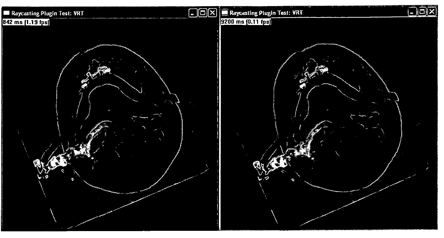
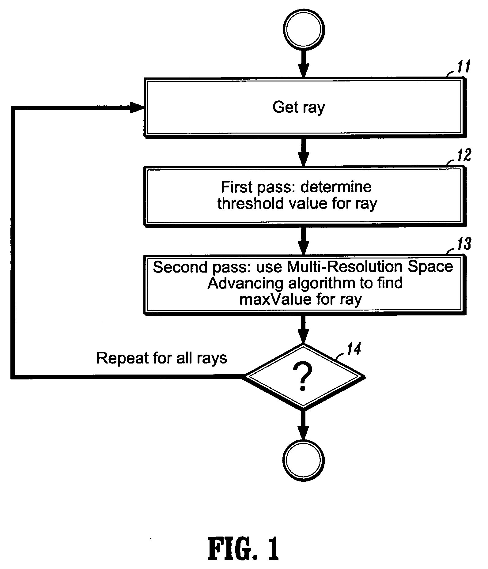
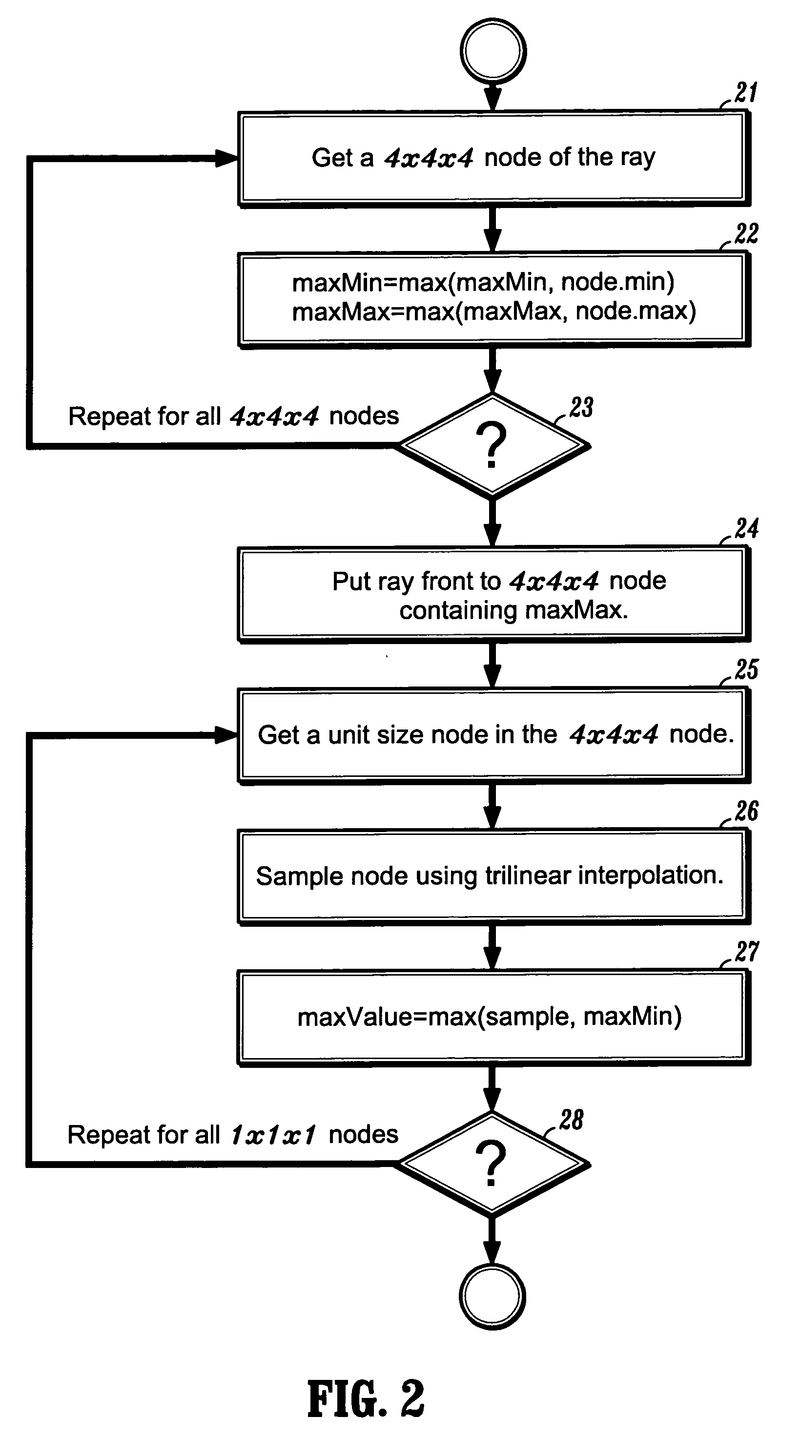
[0005] Exemplary embodiments of the invention as described herein generally include methods and systems for reconstructing a Maximum or Minimum Intensity Projection (MIP / MinIP) using a Multi-Resolution Space Advancing algorithm and a Two-Pass Searching algorithm. The Multi-Resolution Space Advancing algorithm allows a fast skipping of the “empty space” along the ray with minimal overhead, and is disclosed in these inventors' copending application, “System and Method for Fast Volume Rendering”, U.S. patent application Ser. No. 10 / ______, filed concurrently herewith. The Two-Pass searching algorithm uses the Multi-Resolution Space Advancing algorithm to reduce the number of tri-linear interpolations required for a high quality MIP / MinIP by more than 95%. As a result, MIP / MinIP rendering performance is up to 10 times faster without any degradation in image quality and resolution. Interactive performance can be achieved for relatively large dataset without using any special graphics hardware for acceleration.

Problems solved by technology

MIP is intrinsically expensive because it must visit all voxels along the viewing ray to find the maximal value.
Common volume rendering acceleration techniques such as space leaping and early ray termination cannot be applied to MIP.
A brute force high-quality MIP for a 5123 dataset takes about 9-10 seconds on a dual Xeon 3.0 GHZ Dell 450 workstation, which makes it difficult to achieve interactive rendering speed for a high-quality MIP.

Method used


Image

  • System and method for fast generation of high-quality maximum/minimum intensity projections
  • System and method for fast generation of high-quality maximum/minimum intensity projections
  • System and method for fast generation of high-quality maximum/minimum intensity projections

Examples


Embodiment Construction

[0029] Exemplary embodiments of the invention as described herein generally include systems and methods for reconstructing a Maximum or Minimum Intensity Projection (MIP / MinIP) using a Multi-Resolution Space Advancing algorithm and a Two-Pass Searching algorithm. Since the MIP and MinIP are complementary methods, the embodiments described herein invention will be discussed in term of a MIP. It is to be understood that these embodiments can be applied to a MinIP by those skilled in the art.

[0030] As used herein, the term “image” refers to multi-dimensional data composed of discrete image elements (e.g., pixels for 2-D images and voxels for 3-D images). The image may be, for example, a medical image of a subject collected by computer tomography, magnetic resonance imaging, ultrasound, or any other medical imaging system known to one of skill in the art. The image may also be provided from non-medical contexts, such as, for example, remote sensing systems, electron microscopy, etc. Al...


PUM


Abstract

A method for rendering a volumetric image includes providing a digitized volumetric image comprising a plurality of intensities corresponding to a domain of points in a 3-dimensional space, casting a ray through said volumetric image for a first pass to determine a threshold intensity for said ray, casting said ray through said volumetric image for a second pass, and sampling only those points whose intensity value is selected by said threshold intensity to determine a rendering value for said ray, wherein said rendering value is associated with a pixel from which said ray was cast.

Description

CROSS REFERENCE TO RELATED UNITED STATES APPLICATIONS [0001] This application claims priority from “Fast Generation of High-Quality Maximum / Minimum Intensity Projection”, U.S. Provisional Application No. 60 / 583,223 of Lining Yang, et al., filed Jun. 25, 2004, the contents of which are incorporated herein by reference.TECHNICAL FIELD [0002] This invention is directed to volume rendering techniques for extracting structures from digital medical images. DISCUSSION OF THE RELATED ART [0003] Maximum Intensity Projection (MIP) is a known volume rendering technique that is used to extract high-intensity structures from volumetric scalar data, such as a digital medical image. MIP is typically performed as part of a ray casting algorithm, wherein for each pixel of the display device, a ray is cast into the volumetric dataset, and the maximum interpolated value along the ray is selected. At each voxel along the viewing ray, the highest sample value encountered is determined. MIP is commonly u...

Claims


Application Information

Patent Timeline
Patent Type & Authority Applications(United States)
IPC IPC(8): G06K9/00
CPCG06T2210/41G06T15/08
Inventor YANG, LININGXIE, MIN
Owner SIEMENS MEDICAL SOLUTIONS USA INC
Why Eureka
Try Eureka